LTE Module Series
EG21-G Hardware Design
EG21-G_Hardware_Design 50 / 100
Flicker slowly (1800ms High/200ms Low)
Flicker quickly (125ms High/125ms Low)
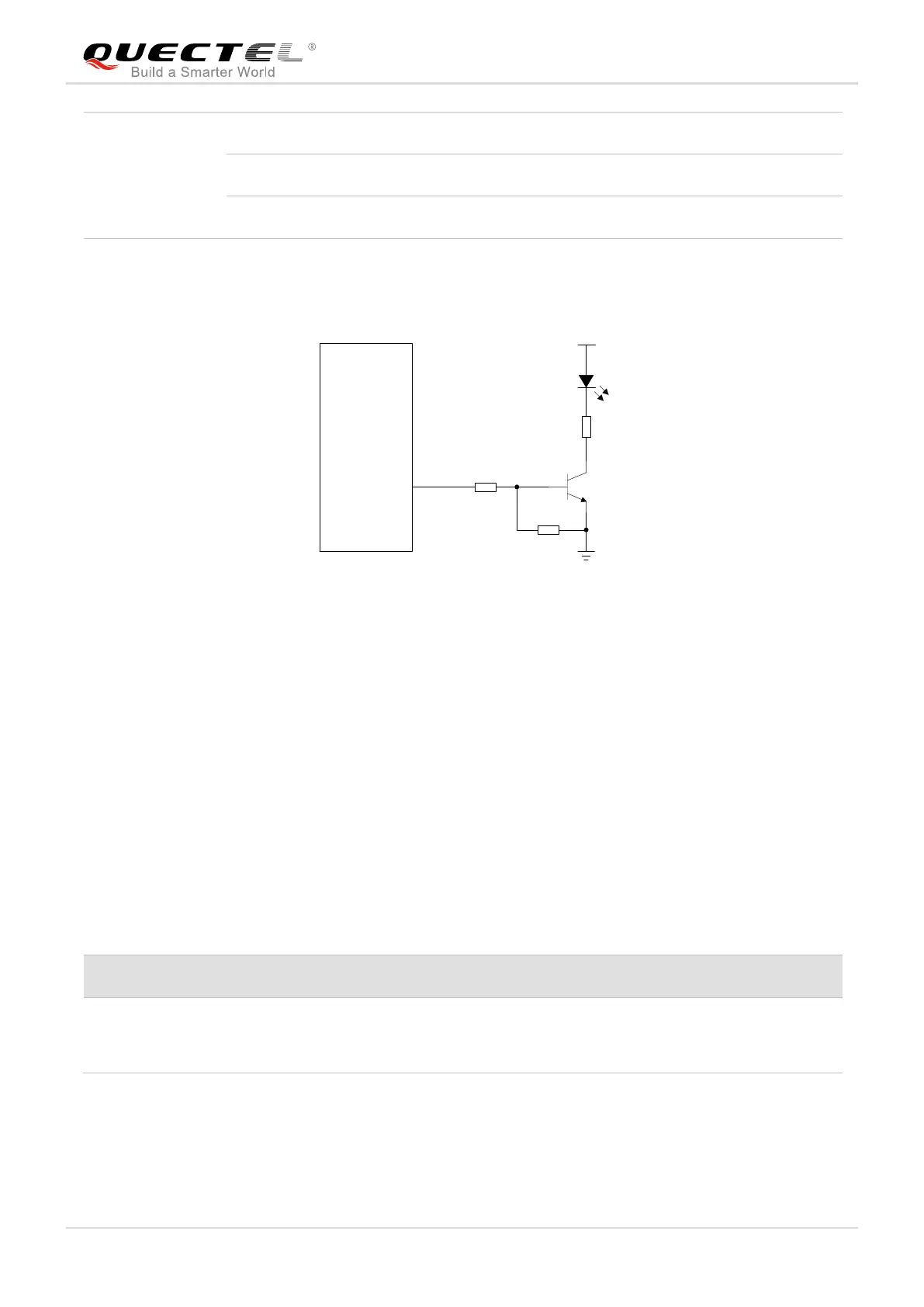
A reference circuit is shown in the following figure.
4.7K
47K
VBAT
2.2K
Module
Network
Indicator
Figure 26: Reference Circuit of the Network Indicator
3.16. STATUS
The STATUS pin is an open drain output for indicating the module’s operation status. It can be connected
to a GPIO of DTE with a pull-up resistor, or as LED indication circuit as below. When the module is turned
on normally, the STATUS will present the low state. Otherwise, the STATUS will present high-impedance
state.
Table 20: Pin Definition of STATUS
Indicate the module operation status
An external pull-up resistor
is required.
If unused, keep it open.
The following figure shows different circuit designs of STATUS, and customers can choose either one
according to customers’ application demands.

 Loading...
