EN
BTQ SERIES INSTALLATION AND USE MANUAL - IT EN - REV001A
24
BTQ series2 - Supplied parts
2.0 - Package contains the following parts
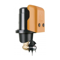
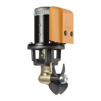
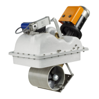
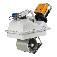
• Thruster
• Drill template
• Gasket
• O-ring (for assembly)
• Installation and use manual
• Conditions of warranty
2.1 - Tools needed for installation
BTQ110/125 • Drill and drill bits Ø 7 mm (9/32”) • Hollow mill Ø 25 mm (1”)
• hexagonal male key 4 mm, 5 mm, 6 mm • Fork or polygonal key 10 mm
BTQ140 • Drill and drill bits Ø 7 mm (9/32”) • Hollow mill Ø 27 mm (1” 1/16)
• hexagonal male key 4 mm, 5 mm, 6 mm • Fork or polygonal key 17 mm
BTQ185 • Drill and drill bits Ø 9 mm (3/8”) • Hollow mill Ø 35 mm (1" 3/8)
• hexagonal male key 5 mm, 6 mm, 8 mm • Fork or polygonal key 19 mm
BTQ250 • Drill and drill bits Ø 11 mm (7/16”) • Hollow mill Ø 46 mm (1” 13/16)
• hexagonal male key 4 mm, 5 mm, 8 mm,10 mm • Fork or polygonal key 24 mm
BTQ300 • Drill and drill bits Ø 15 mm (19/32”) • Hollow mill Ø 53 mm (2” 3/32)
• hexagonal male key 4 mm, 5 mm, 8 mm, 12 mm • Fork or polygonal key 27 mm
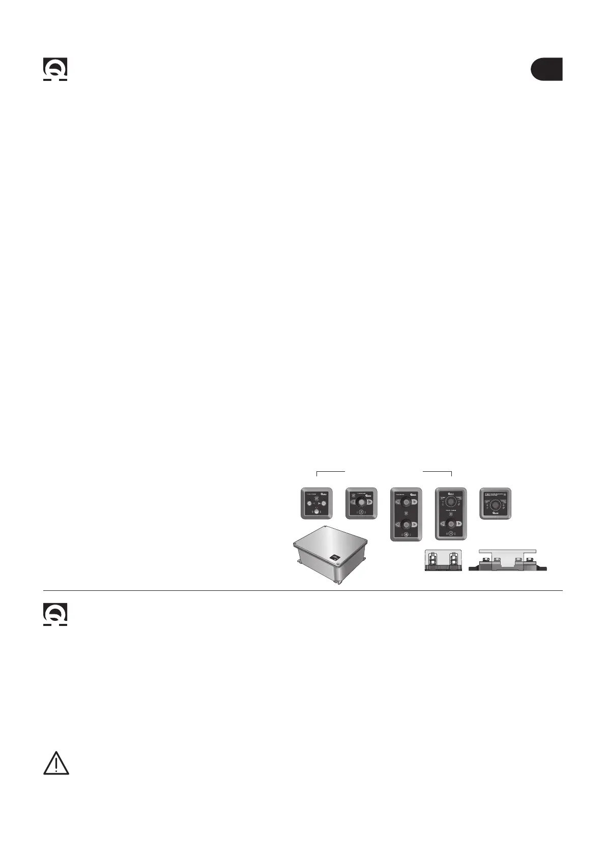
2.2 - “Quick®”accessories recommended
• Remote control TCD 1022
• Remote control TCD 1042
• Remote control TCD 1044
• Remote control TCD 1062 with integrated
line switch control
• TSC Thruster Main Switch Command
• TMS line switch control
• THF3 - THF6 fuseholders
3 - Introduction BTQ series
BEFORE USING THE THRUSTER READ THESE INSTRUCTIONS CAREFULLY.
IF IN DOUBT, CONTACT YOUR NEAREST “QUICK®” DEALER.
This document contains the instructions that are necessary for boat manufacturers and
marine equipment installers to assemble and commission
the Thruster.
Warning symbol concerning hazard-
ous situations.
Caution
symbol to avoid direct or
indirect damage to the product.
This manual contains Warning and/or Caution symbols that are important for safety.
Comply with the recommendations provided herein.
3.0 Important notes
F
THRUSTER
MAIN SWITCH
COMMAND TSC
TMS THRUSTER
MAIN SWITCH
TCD 1022 TCD 1042
STERN
BOW
TCD 1044 TCD 1062
CONTROL PANELS
 Loading...