EN
BTQ SERIES INSTALLATION AND USE MANUAL - IT EN - REV001A
31
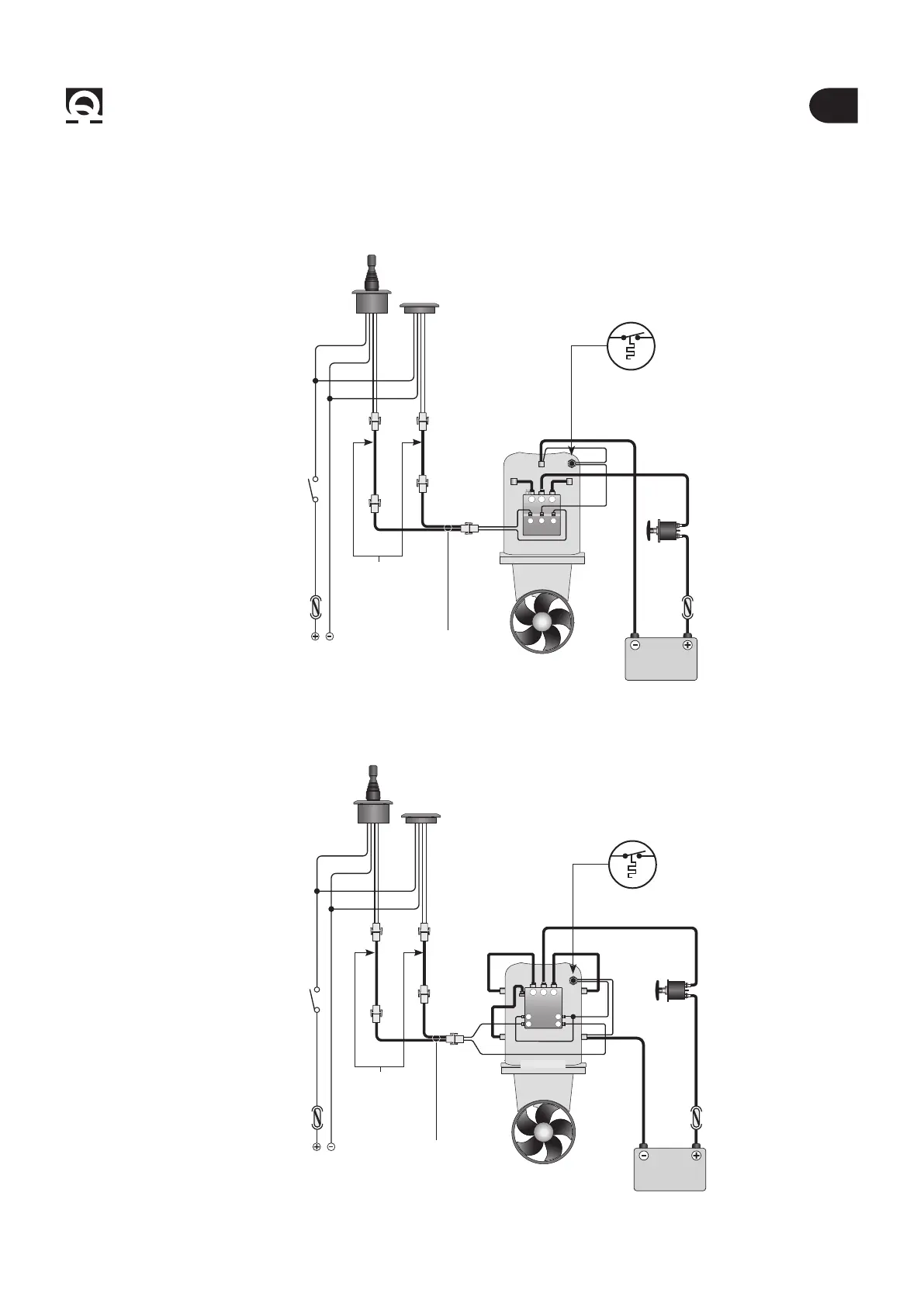
BTQ series6 - Connection diagram
TO THE SERVICES BATTERY
TO THE SERVICES BATTERY
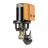
6.0 - Basic System BTQ110
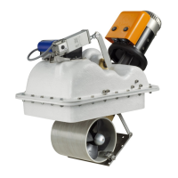
6.1 - Basic System BTQ125
* Common negative for the battery groups.
** WARNING: in case of overtemperature, the thermal protection on the motor will open and interrupt the negative contact on the solenoid
unit. Wait as long as the system needs to reactivate.
Example of connection
Example of connection
M1
A
S
SX
+
DX
-
M2
A
M1
A A
S S
SX
+
-
DX
-
M2
MOTOR
MOTOR
BATTERY
12/24V
BATTERIA
12/24V
BLACK
BLACK
FUSE
4A FAST
FUSE
4A FAST
FFUSE
SEE TABLE ON
PAGE 22
FFUSE
SEE TABLE ON
PAGE 22
SWITCH
SWITCH
RED
RED
BLACK
BLACK
RED
RED
SPLITTER
(OPTIONAL)
SPLITTER
(OPTIONAL)
EXTENSION CABLE
(OPTIONAL)
EXTENSION CABLE
(OPTIONAL)
*
*
*
*
**
**
TCD
TCD
TCD
TCD
THERMIC
PROTECTION
THERMIC
PROTECTION
BATTERY ISOLATOR
BATTERY ISOLATOR
 Loading...