EN
BTQ SERIES INSTALLATION AND USE MANUAL - IT EN - REV001A
32
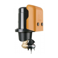
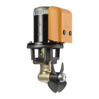
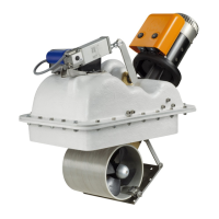
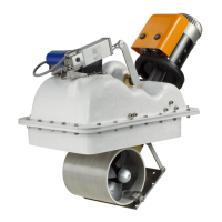
BTQ series
M1
A A
S S
SX
+
-
DX
-
M2
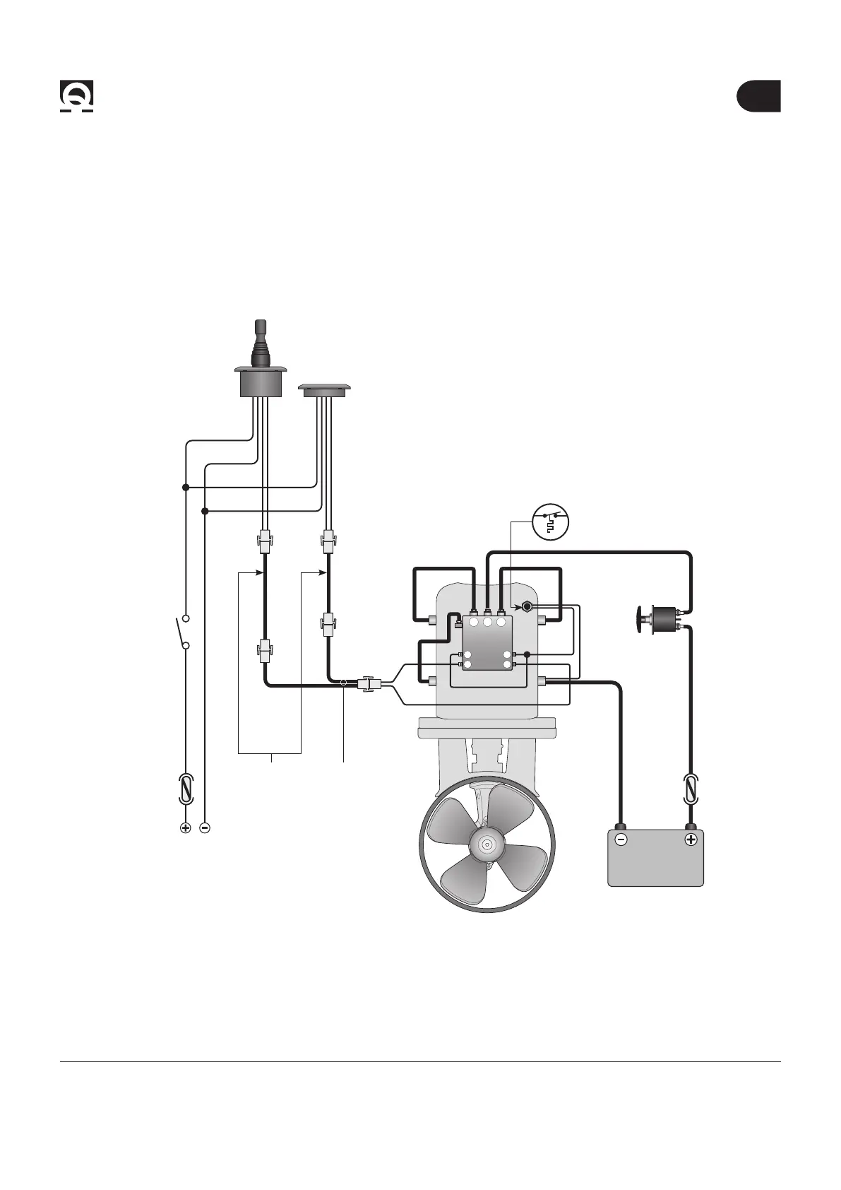
6 - Connection diagram
Control panel
To install the control panel, consult the “TCD” instruction manuals.
FUSE
4A FAST
SWITCH
TO THE SERVICES BATTERY
THERMIC
PROTECTION
6.2 - BTQ140/185/250/300 Basic System
Example of connection
MOTOR
BATTERY
12/24/48 V
BLACK
RED
BLACK
RED
*
*
TCD
TCD
**
SPLITTER
(OPTIONAL)
EXTENSION CABLE
(OPTIONAL)
* Common negative for the battery groups.
** WARNING: in case of overtemperature, the thermal protection on the motor will open and interrupt the negative contact on the solenoid
unit. Wait as long as the system needs to reactivate.
BATTERY ISOLATOR
 Loading...