7
SECTION II
DESCRIPTION
1. General Description of Quincy QSVB Series Vacuum Pumps
The QSVB line of rotary screw vacuum pumps covers the horsepower range of 7.5 to 25 horsepower. The vacuum
pump is a single stage, positive displacement, and fluid-flooded rotary screw type unit. The vacuum pump consists of
two precision machined rotors. The drive rotor is driven through a “V” belt arrangement.
An external fluid pump directly driven by the female rotor maintains fluid circulation. All components are attached
to a heavy-duty steel frame. Controls and indicators are arranged on a control panel.
2. Principles of Vacuum Pump Operation
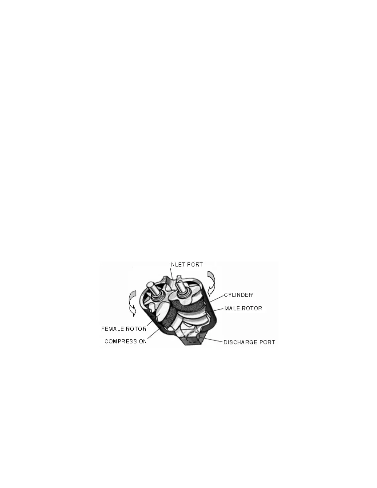
The compression cycle of a rotary vacuum pump is a continuous process from intake to discharge with no
reciprocating mechanisms starting and stopping as found in reciprocating vacuum pumps. The vacuum pump
consists of two rotors in constant mesh, housed in a cylinder with two parallel adjoining bores. The male drive rotor
has four lobes that mesh with six flutes in the female rotor. All parts are machined to exact tolerances.
As the rotors rotate, (clockwise as viewed from the power-input end) air is drawn into the cylinder through the inlet
port located at the power-input end. A volume of air is trapped as the rotor lobes pass the inlet cut off points in the
cylinders. Compression occurs as the male rotor rolls into the female flute, progressively reducing the space thereby
raising the pressure. Compression continues until the lobe and flute pass the discharge port. The air is then
discharged into the air/fluid reservoir where it is discharged to the atmosphere through the fluid separator element.
There are four complete compression cycles for each complete rotation of the male rotor. (Figure 2-1).
Figure 2-1
 Loading...