THERMO SAFETY ALARM
The unit incorporates a thermo safety shut-off. In the event of electron-
ic failure, an internal “snap disc” will cut off power to the unit until it is
manually reset. To reset oven, unplug the unit, locate ‘SNAP DISC
HOLE PLUG’ (FIG. 6) in the back of the unit. Remove plug and with
a NON-METEAL rod press on the button to reset.
WARNING:
Safety Alarm Reset
REMOVE SNAP DISC HOLE
PLUG TO ACCESS SAFETY
RESET DISC BUTTON.
RISK OF ELECTRICAL SHOCK. DISCONNECT UNIT FROM POWER
SOURCE BEFORE REMOVING COVER. FAILURE TO COMPLY COULD
RESULT IN SERIOUS INJURY OR DEATH.
Read Operating Instructions thoroughly prior to operation and observe the following safety precautions:
Use only a grounded outlet that is rated for your model's electrical requirement.
Do not modify the oven or factory control settings to operate the oven above the stated maximum operating temperature.
Exterior surfaces on the Bench Oven models may become hot to the touch when operating at higher set temperatures.
Do not leave the oven unattended during operation.
Conduct periodic maintenance as required.
WARNING: Do not place volatile or combustible materials into Bench Ovens.
CAUTION: This unit is not intended for use with any flammable solvents or vapors, or with chemicals that produce toxic gases.
Connecting to the Exhaust Chamber Adapter (Optional)
The optional exhaust chamber adapter is used to vent oven chamber fumes and heated moisture-laden air to a building's
exterior for the purposes of minimizing excess heat, humidity or unpleasant but otherwise harmless fumes within an
interior working environment.
The exhaust chamber system as a whole is not designed for use to remove harmful
or flammable gases or vapors since the oven itself is not rated for use with such materials
It is recommended that the attached exhaust chamber and piping be checked once a year for any obstruction from dust,
dirt, or material process "plaque" build-up from processing certain materials. Check with the manufacturer of the
materials used in your process if heating the material may produce a bi-product or out gassing that may build up on the
interior surface of the oven, exhaust chamber or piping and present a fire hazard over time.
Contact an HVAC engineer for assistance with installation or questions regarding proper venting requirements
in your specific building or location, and if any local or national fire or safety codes may apply for your application
or process.
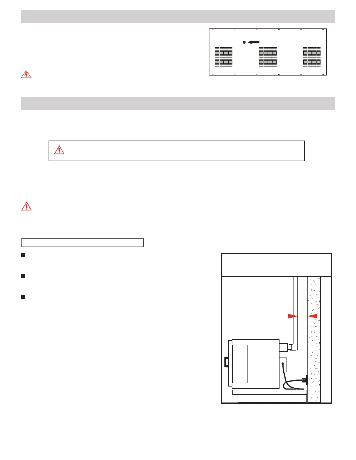
Connect the exhaust chamber adapter with standard 3" or 4" diameter
single or double-wall steel or galvanized pipe.
A minimum of 4 inches of clearance should be maintained between the
connected pipe and any building surface or material. (FIG. 7)
For best performance, run a short pipe horizontally (3 feet max.) directly
through an exterior wall.
For vertical runs the exhaust pipe should not have more than one (1) 90
degree elbow, a maximum horizontal run of 3', and a maximum of 15' verti-
cally. Exceeding these recommendations may cause improper ventilation.
Poor exhaust quality would be indicated by an excess of fumes and or
vapor from around the door gasket versus what would normally be present
if no exhaust venting was used.
Piping run lengths can be extended beyond recommended maximums
where a connection to an existing ventilation or exhaust system provide a
larger pipe diameter and/or a mechanically powered draft that provides a
negative pressure at the point of connection. Mechanically powered vent
systems work best to eliminate fumes and moisture vapors, but depending
on vacuum strength at the point of connection, it may slightly reduce the
oven's time-to-temperature and recovery performance.
CONNECTING TO THE EXAHUST ADAPTER
WALL
4"
CLEARANCE
REQUIREMENTS
4" minimum from wall
to rear exhaust piping.
PAGE 5
FIG. 6
UNITS REAR ELECTRICAL COVER
FIG. 7
 Loading...