Chapter 1
2 TM-1 Tilt Module Installation & Reference Manual
computer. The Raven TM-1 Tilt Module is designed be compatible with any GPS receiver which supports serial
output via a DB-9 style connector.
Note: In order to properly compensate latitude and longitude position, the TM-1 requires a valid course-
over-ground (COG) from the GPS receiver. Typically, the COG is only valid while the machine is in
motion. The TM-1 automatically stops compensating position messages if the reported machine
speed falls below the speed required for valid COG measurements.
The TM-1 reports tilt angle as negative for a tilt to the left and positive for right-leaning tilts. The
maximum tilt angle which the TM-1 may register is ±45° from a level surface.
Kit Contents
Refer to the following table for the contents of the TM-1 Tilt Module kit (P/N 117-0171-059).
Note: The input and output connectors are standard DB-9 serial connectors which work with all Raven
equipment and should be compatible with all other GPS receivers which provide serial output.
Hardware & User Interface
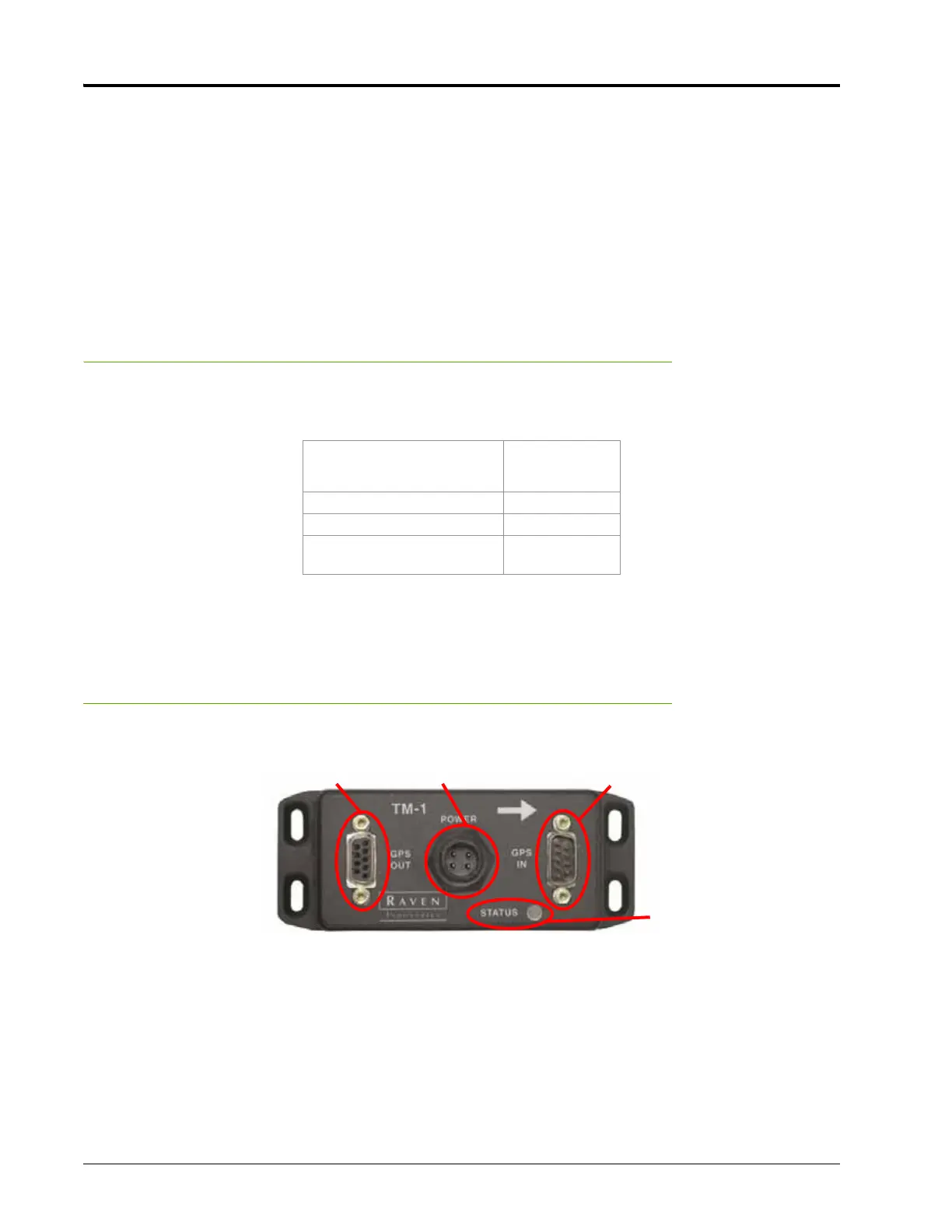
The TM-1 Tilt Module unit has 3 connectors and a status indicator light.
Since the TM-1 does not have a user interface, the TM-1 will need to be configured using a serial connection
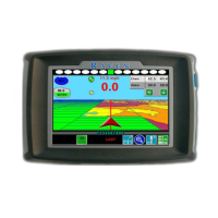
on a laptop, SmarTrax™ controller, or a Raven field computer.
• Viper II™ or Viper Pro™
• Envizio Pro™ or Envizio Pro II™
• Envizio™ (software versions 2.0 or newer) or Envizio Plus™
• Cruizer™ or Cruizer II™
Refer to Chapter 3, TM-1 Set Up & Configuration, for information on configuring the TM-1 Tilt Module using any
one of the above methods.
Component Part Number
Sensor, TM-1 Tilt 063-0172-683
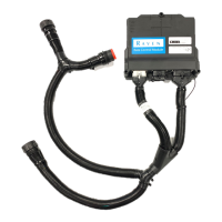
Cable, Power, 144” 4-Pin 420-1001-701
Cable, Tilt Interface 115-0171-754
Manual, Installation &
Reference, TM-1 Tilt Module
016-0171-049
GPS Output 4-Pin Power GPS Input
Status Indicator
 Loading...