EasyManua.ls Logo

Raymarine 530 User Manual

Raymarine 530
170 pages
To Next Page IconTo Next Page
To Previous Page IconTo Previous Page
Page #3 background imageLoading...
Page #3 background image
iii
SL520/530/631 PLUS Chartplotter Display
Owner’s Handbook
September 2002
INTENDED USE
The display units detailed in this handbook may form part of navigational
radar systems intended for light marine use. These displays and radar
systems are only an aid to navigation.
SAFETY NOTICES
This equipment must be installed and operated in accordance with the
instructions contained in this manual. Failure to do so can result in personal
injury and/or navigational inaccuracies. In particular:
1. HIGH VOLTAGE. The LCD display unit unit contains high voltages.
Adjustments require specialized service procedures and tools only
available to qualified service technicians – there are no user serviceable
parts or adjustments. The operator should never remove the display unit
cover or attempt to service the equipment.
2. NAVIGATION AID. This unit is only an aid to navigation. Itsaccuracy can
be affected by many factors, including equipment failure or defects,
environmental conditions, and improper handling or use. It is the user’s
responsibility to exercise common prudence and navigational judgements.
This unit should not be relied upon as a substitute for such prudence and
judgement.

Table of Contents

Question and Answer IconNeed help?

Do you have a question about the Raymarine 530 and is the answer not in the manual?

Raymarine 530 Specifications

General IconGeneral
BrandRaymarine
Model530
CategoryGPS
LanguageEnglish

Summary

SL520/530/631 PLUS Chartplotter Display Owner's Handbook

Intended Use

Safety Notices

Preface

TFT Color LCD Displays

Discusses display variations, pixel behavior, and UV protection advice.

Warranty Information

Explains the process for registering display unit ownership for warranty benefits.

EMC Conformance

Chapter 1: Overview

How to Use This Handbook

Guides the user on how to navigate and utilize the handbook effectively.

General Product Information

Offers a general overview of the display unit's features and capabilities.

The Chartplotter Display

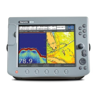
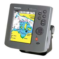
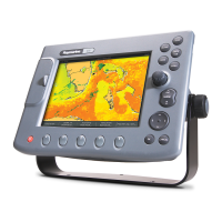
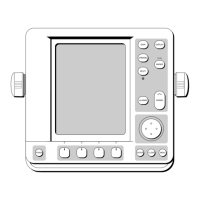
Details the chartplotter screen layout, data display, and zoom functions.

Operating Controls Overview

Introduces the various controls used to operate the chartplotter system.

Terminology

Master Unit Definition

Explains a unit capable of sourcing specific data, such as chart data.

Radar Display Definition

Defines a unit providing Radar Master functionality.

Chart Display Definition

Defines a unit providing Chart Master functionality.

Integrated System Definition

Describes additional instruments connected via SeaTalk or NMEA interfaces.

Chapter 2: Getting Started and Adjusting the Display

Chapter 2 Introduction

Provides an overview of the chapter's content and how to use the display.

Handbook Conventions

Explains the conventions used for keys, menus, and procedures throughout the handbook.

Simulator Functionality

Describes the simulator function allowing practice without live GPS data.

Adjusting Lighting and Contrast (SL520 Mono)

Adjusting Brightness (SL530/631 Color)

Controlling the Display

Selecting Display Mode of Operation

Guides on how to select between full-screen modes like Chart and Data Log.

Selecting Half-Screen Windows

Returning to Full-Screen Display

Chart Display Control Functions

Moving Around the Chart

Covers methods to pan, zoom, and center the chart display for examination.

Customizing Screen Presentation Options

Cursor Data Box On/Off

Explains how to toggle the visibility of the cursor's position data box.

Chart Grid On/Off

Details how to enable or disable the latitude and longitude grid lines on the chart.

Typical Chart Scenarios

Chapter 3: Standard Chart Operations

Chapter 3 Introduction

Introduces the use of chart functions for navigation and lists chapter topics.

Navigational Safety Guidelines

Emphasizes safe navigational practices and comparing displayed objects with visual targets.

Using Chart Cards

Inserting a Chart Card

Provides step-by-step instructions for inserting a C-MAP NT electronic chart card.

Removing a Chart Card

Displaying Chart Data

Displaying Chart Object and Source Information

Port Area Information

Tide Data Display

Working with Waypoints

Placing a Waypoint

Selecting a Waypoint

Waypoint Data Display

Editing Waypoint Details

Erasing a Waypoint

Moving a Waypoint

Using the ST60/ST80 Navigator Keypad

Working with Routes

Creating a New Route

Saving the Current Route

Clearing the Current Route

Retrieving a Route From the Database

Displaying Route Information

Editing a Route

Following Routes and Going to Points

Following a Route

Details how to follow the current route forwards or in reverse order.

Target Point Arrival

Joining a Route

Advancing to a Waypoint

Restarting Cross Track Error (XTE)

Going To an Individual Target Point

Stop Follow or Stop Goto

Transferring Waypoints and Routes

Displayed SeaTalk Waypoints

Discusses how routes are shared across SeaTalk instruments and their editability.

Managing Database Lists

Covers methods for maintaining waypoint and route lists via cartridges or transfers.

Saving/Loading Waypoints to/from User Cartridge

Using Tracks

Accessing Track Controls

Guides on how to access track setup options via the MENU and TRACK SETUP soft keys.

Setting Up a Track

Clearing the Current Track

Managing Tracks

SmartRoute Functionality

Chapter 4: Further Chart Operations

Chapter 4 Introduction

Introduces additional chartplotter display functions and required external data.

Measuring Distances Using VRM/EBL Key

Alarms and Timers

Alarm Reporting

Lists and describes the various alarms the chartplotter can report.

Setting Alarms and Timers

Man Overboard (MOB) Function

Cursor Echo Functionality

GPS Setup

Selecting GPS Setup

Details how to access the GPS setup menu for status and configuration.

Restarting GPS

D-GPS Set Up

Data Log Mode

Activating Data Log Mode

Explains how to enable and activate the data logging function.

Chapter 5: Setting Up the System Defaults

Chapter 5 Introduction

Introduces the process of setting up the system according to user preferences.

Changing Setup Parameters

Setting Default Parameters

Guides on navigating menus and selecting desired settings for system parameters.

System Set Up Parameters

Data Boxes Configuration

Bearing Mode Setting

Cursor Reference Setting

Cursor Readout Options

Day/Night Mode Setting

Help Functionality

Soft Keys Behavior

Key Beep Control

MOB Data Source Setting

Autopilot Pop Up Display Control

Menu Timeout Period Setting

Units Configuration

Variation Source Setting

Bridge NMEA Heading Option

NMEA Out Set Up

Cursor Echo Setup

Date and Time Settings

GPS SOG/COG Filter Setting

Compass Set Up

Language Selection

Simulator Mode Options

Chart Set Up Parameters

Customize Chart Options

Allows specifying how chart features like text, boundaries, and icons are displayed.

Plotter Mode Setting

Chart Orientation Settings

Object Information Settings

Waypoint Options

Vectors Display Settings

Radar/Chart Synchronization

Datum Selection

Position Offset Adjustment

Chapter 6: Installation

Chapter 6 Introduction

Provides installation instructions for the display unit and connected equipment.

Planning the Installation

EMC Installation Guidelines

Suppression Ferrites

Connections to Other Equipment

Unpacking and Inspecting Components

Selecting the Display Unit Location

Convenience Considerations

Discusses viewing angle impact and selecting a suitable, accessible mounting location.

Access Requirements

Highlights the need for sufficient space behind the display for cable connections.

Interference Avoidance

Advises selecting a location away from devices that may cause electromagnetic interference.

Magnetic Compass Clearance

Specifies the minimum distance required from a magnetic compass for proper operation.

Cable Run Planning

Notes the requirement for proximity to a DC power source and cable length.

Environmental Considerations

Advises on ensuring adequate ventilation and protecting the unit from damage and vibration.

Cable Runs

Power Cable Installation

Details the power cable connection for 12V, 24V, or 32V DC systems and wire gauge considerations.

Mounting the Display Unit

Mounting Bracket Installation

Provides instructions for attaching the display unit using the supplied mounting bracket.

Console Mounting

Explains how to mount the display unit using the optional flush-mounting kit.

System Connections

Grounding the System

Details the importance and procedure for connecting an effective RF ground to the system.

DC Power Connection

Outlines how to connect the display unit to the ship's DC power system.

Power for External Equipment

Clarifies that external equipment must be powered from the ship's supply, not the display's SeaTalk.

Display Unit Connection

Power and NMEA Input Connection

System Checks and Initial Switch On

System Check Procedures

Lists checks to perform before the functional test to ensure proper installation.

Initial Switch On and Setup

Guides on switching on the unit and performing initial setup steps like language.

EMC Conformance Check

Integrated Systems

Power for External Equipment

Details power requirements for external equipment connected via SeaTalk.

SeaTalk and NMEA Data Input

SeaTalk Protocol Overview

Describes the SeaTalk standard as a flexible, high-speed bi-directional protocol.

SeaTalk Connection Details

NMEA 0183 Standard

NMEA Input Connection

Using the SeaTalk Auxiliary Junction Box

Data Output

Data Conversion

Integrated System Checks

Chart Display Checks

Outlines checks to ensure the chart display operates correctly with position data and chart cartridges.

Received Data Verification

Guides on verifying that expected data is displayed from SeaTalk or NMEA inputs.

Transmitted Data Verification

Explains how to check if transmitted data via NMEA Out is being received correctly.

Chapter 7: Maintenance and Problem Solving

Routine Maintenance

Lists periodic checks for cleaning, cable inspection, and connector security.

Cleaning Instructions

Provides specific instructions and cautions for cleaning the display screen safely.

EMC Servicing and Safety Guidelines

Emphasizes that Raymarine equipment should only be serviced by authorized technicians.

Resetting the System

Factory Reset Procedure

Explains how to reset all values to original factory settings, including clearing databases.

Power-On Reset Behavior

Describes how the screen reverts to chart picture after a power cycle.

Picture Reset Function

Explains how to use the DISPLAY key to return the screen to full-screen top window.

Problem Solving

Common Problems and Solutions

Provides a table of common issues and their corrective actions.

Technical Support Contact Information

Lists website and phone numbers for Raymarine technical support.

How to Contact Raymarine (US)

Marine Product & Services Info (US)

Directs users to the Raymarine website for the latest product and system information.

Accessories and Parts Contact (US)

Provides contact details for obtaining accessory items and parts directly.

Product Repair and Service (US)

Outlines procedures and contacts for product repair and service through dealers or the repair center.

How to Contact Raymarine (Europe)

European Support and Service

Provides contact details for Raymarine support, service, and accessories in Europe.

Worldwide Support Network

Advises contacting authorized distributors in the country for worldwide support.

Appendix A: Specifications

General Specifications

Lists general approvals, size, weight, mounting, and power requirements for the displays.

Chartplotter Features Overview

Interfacing Capabilities

Appendix B: C-MAP Chart Card Features

Appendix C: SeaTalk and NMEA Data

Appendix D: Abbreviations

Warranty Certificate

Limited Warranty Terms

Outlines Raymarine's warranty for materials and workmanship for a specified period.

Installed Warranty Coverage

Details warranty cover for onboard service, including travel costs and time.

Obtaining Warranty Service Process

Explains how to contact Raymarine or service agents and what proof is needed for warranty service.

Warranty Limitations and Exclusions

Lists conditions under which Raymarine's warranty policy does not apply.

Factory Service Centers

United States Service Centers

Lists Raymarine service centers, sales, technical support, and repair contacts in the USA.

UK, Europe, Middle East, Far East Service Centers

Lists Raymarine service centers and customer support contacts for Europe and the Middle East.

Related product manuals