Wind Vane Service Manual 9
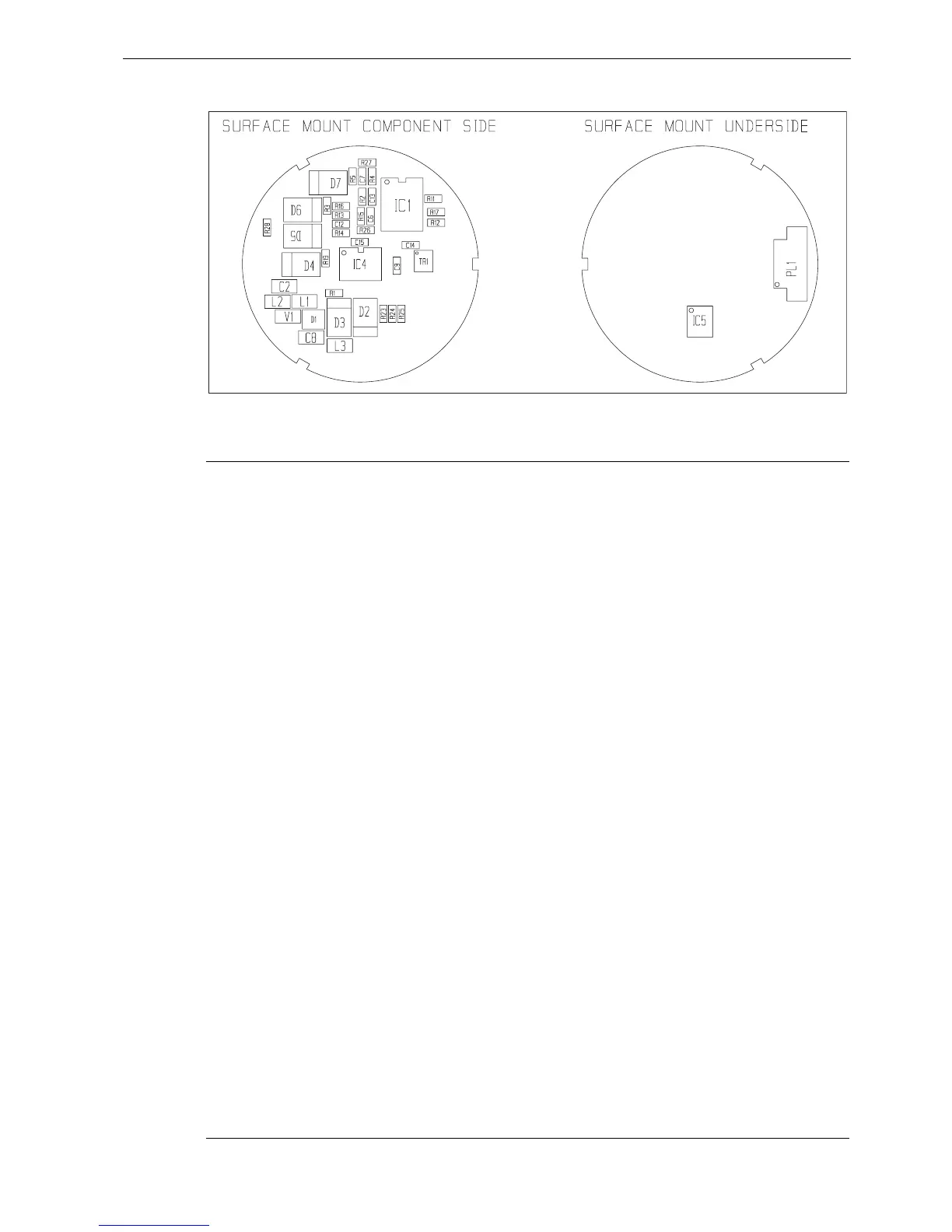
Layout diagram
Component List
Reference Part No. Description
3015-329-C WIND TX PCB
C2 93CKEIXXX10U CAP CER 10uF 16V
C6 93ADHBXX10N CAP. 10nF XR7
C7 93ADHBXX10N CAP. 10nF XR7
C8 93CKEIXXX10U CAP CER 10uF 16V
C9 93ADHBXX10N CAP. 10nF XR7
C12 93ADHBXX10N CAP. 10nF XR7
C13 93ADHBXX10N CAP. 10nF XR7
C14 93ADHBXX10N CAP. 10nF XR7
C15 93ADHBXX10N CAP. 10nF XR7
D1 9200BAT54 BAT54 SCHOTTKY DIODE
D2 9200ES2B DIODE ES2B
D3 9200ES2B DIODE ES2B
D4 9200ES2B DIODE ES2B
D5 9200ES2B DIODE ES2B
D6 9200ES2B DIODE ES2B
D7 9200ES2B DIODE ES2B
IC1 9400TS914 QUAD OPAMP
IC4 94002SA10 DUAL AXIS HALL Do NOT attempt to replace or otherwise disturb IC4
IC5 9400TCPT1200 OPTO SURFACE MOUNT
L1 9600L1 CHIP INDUCTOR
L2 9600L1 CHIP INDUCTOR
L3 9600L1 CHIP INDUCTOR
PL1 9600MOL53398 CONNECTOR
R1 91AAAXX470R RESISTOR 470R,1% 0.063W 0603
D6957-1 (From Drawing No. 4531-001B)

 Loading...