Illustrations contained in this document are for representation only.
Connections and Setup
Fr
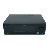
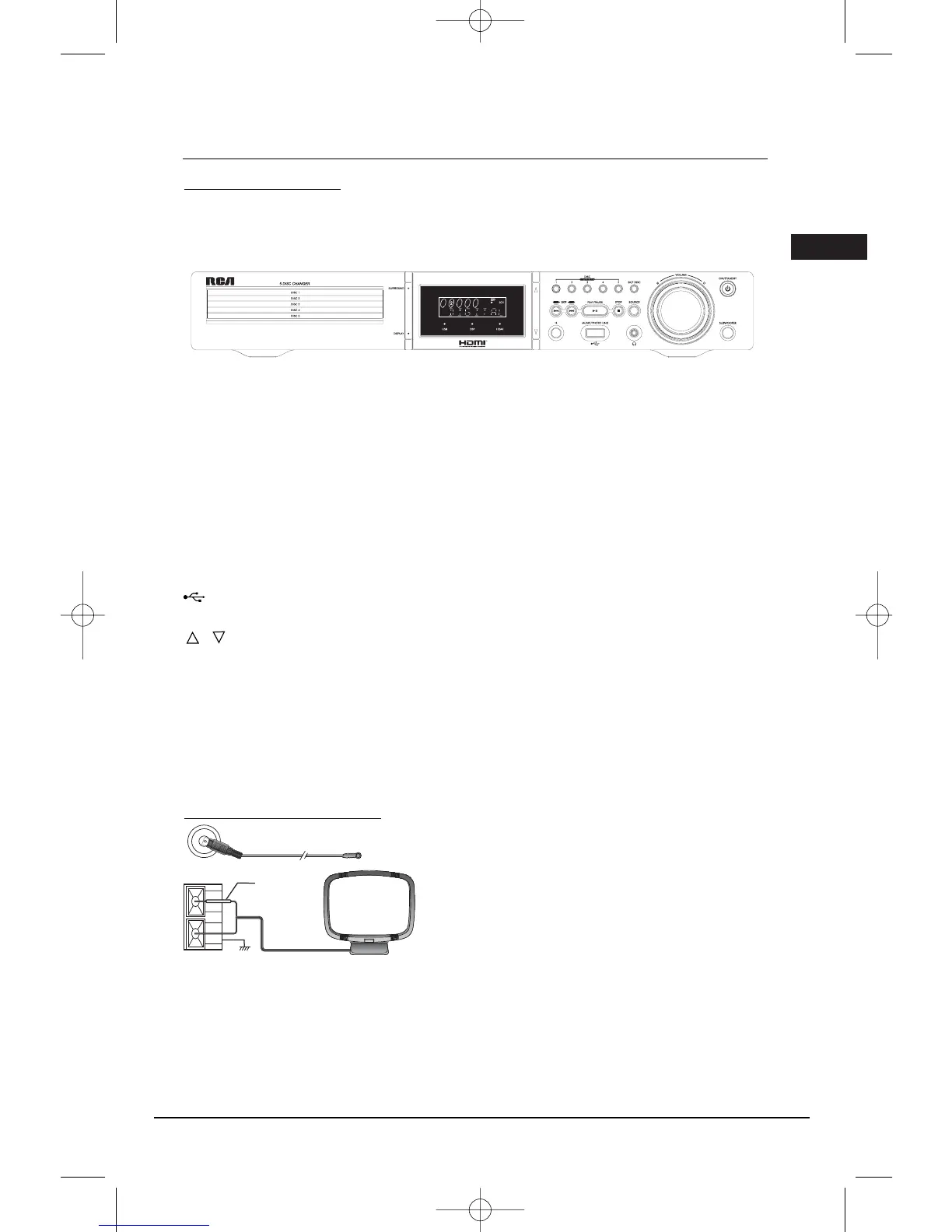
ont panel controls
ON/STANDBY - Switches the unit on and off.
SUBWOOFER - Toggles between different subwoofer output levels (soft/balance/strong/powerful).
VOLUME - Adjusts the volume.
DISC SKIP – Goes to the next slot in the disc tray.
OPEN/CLOSE DISC 1/2/3/4/5- Opens and closes the disc tray according to the disc tray number.
SOURCE - Selects the input source.
STOP - Stops disc playback.
PLAY/PAUSE - Starts playing a disc. Pause.
SKIP BWD/FWD - Skips to the previous and the next track or file.
HEADPHONE JACK - Inserts headphone here
MUSIC/PHOTOLINK - Connects USB devices for playing music and photos.
IR - Connects infra-red devices for remote control.
/ - Navigate buttons which move through on-screeen menus.
SURROUND - Changes the Surround sound setting and DSP mode setting.
DISPLAY - Accesses the INFO menu.
USB light indicator - Indicates USB mode is activated.
DSP light indicator - Indicates DSP mode is activated.
HDMI light indicator - Indicates HDMI mode is activated.
Connecting the Antennas
The AM and FM antennas connect to the AM and FM
terminals on the system’s back panel.They must be hooked
up in order to receive clear reception.
AM Loop Antenna and FM Indoor Antenna
1. Uncoil the AM Antenna wire.
2. Press down on the Antenna tab to open the terminal
Note: Make sure the white wire on the AM lop antenna is inserted into
the left terminal.
3
 Loading...