14 | Installation
2.3 Input Trigger Settings — Blue Wire
Connect the BLUE wire to switch the vehicle input turn-ON-trigger mode between:
• Standard Trigger (for fixed voltage or temperature compensating alternators)
• Low Voltage Trigger (for variable voltage alternators)
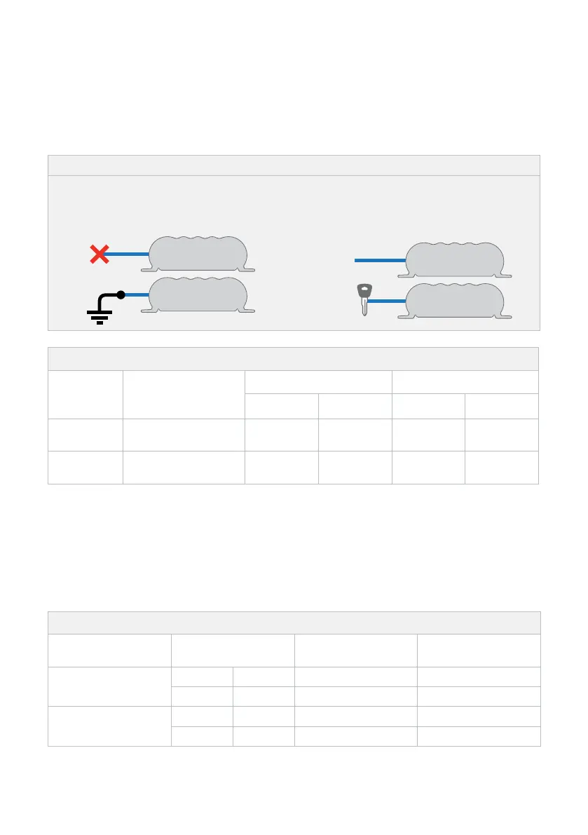
Figure 2.3.1: Connecting the BLUE wire
STANDARD TRIGGER
Leave and tape over the disconnected
BLUE wire, or connect to Ground.
LOW VOLTAGE TRIGGER
Connect the BLUE wire to D+ for Idle-stop
vehicles, or IGN for continuous Idle vehicles.
Vehicle
Ignition
D+
Table 2.3.2: Setting the Input Trigger Settings
*1
Input Mode
Blue Wire
Connection
12V Mode 24V Mode
ON above OFF below ON above OFF below
Standard
Not Connected, or
Connected to Ground
12.9V 12.7V 25.8V 25.4V
Low
Voltage
D+ for Idle-Stop
'Ignition' for others
12.0V 11.9V 24.0V 23.8V
*1 Tested every 100 seconds
2.4 Cable sizing
Refer to "Table 2.4.1: Cable Sizing" for the Vehicle Input, Solar Input, Ground and Battery Output
cable thickness and length requirements. Always choose a wire cross sectional area equal to or
greater than what is specified.
Table 2.4.1: Cable Sizing
Part Number Cable Install Length
Wire Cross
Sectional Area
Nearest Equivalent
BAE, B&S, AWG
BCDC1225D
1 – 5 m 3' – 16' ≥7.71 mm² 8
5 – 9 m 16' – 30' ≥13.56mm² 6
BCDC1240D
BCDC1250D
1 – 5 m 3' – 16' ≥13.56mm² 6
5 – 9 m 16' – 30' ≥20.28mm² 4

 Loading...