9
2 INSTALLATION
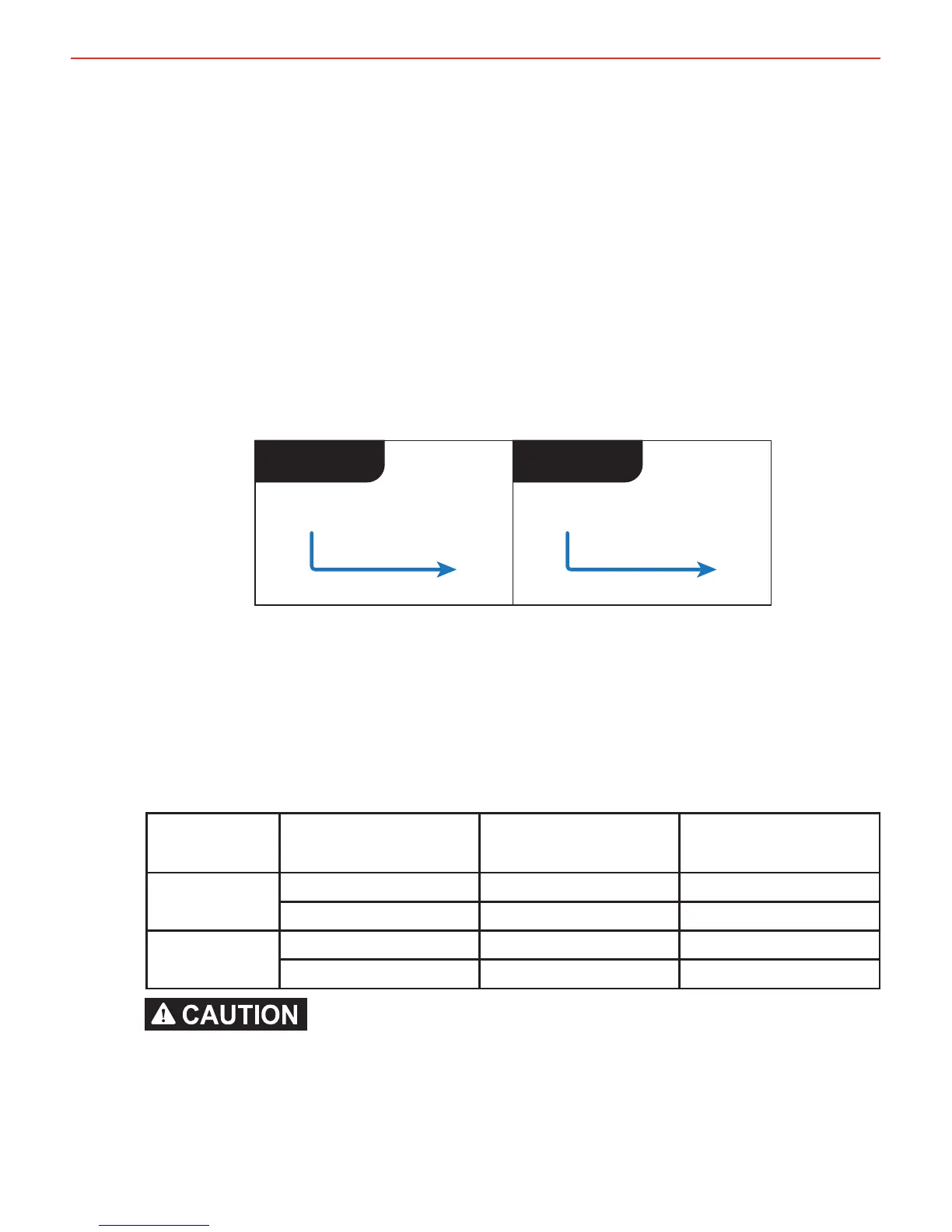
2.3 Input Trigger Settings (BLUE Wire)
The BLUE wire is used to select between the Standard turn ON trigger settings
and the Low Voltage turn ON trigger settings (suitable for Variable Voltage and
Smart Alternators) on the Vehicle Input.
Standard trigger settings: Leave the BLUE wire disconnected.
This will set the trigger settings to 13.2V turn ON and 12.7V turn OFF for a 12V
installation or 26.4V turn ON and 25.4V turn OFF for a 24V installation.
Low Voltage trigger settings: Connect the BLUE wire to the Vehicle Ignition.
This will set the trigger settings to 12.0V turn ON and 11.9V turn OFF when
Ignition is ON for a 12V installation or 24.0V turn ON and 23.8V turn OFF
when Ignition is ON for a 24V installation.
Standard Low Voltage
Vehicle
Ignition
Blue Wire
Not
Connected
Blue Wire
Figure 2.3.1 - Setting the Input Trigger Settings
2.4 Cable sizing
Below is a table outlining the required cable size for a given cable install length.
Please refer to this table for Vehicle Input, Solar Input, Ground and Battery Output
cable thickness requirements.
Always choose a wire diameter equal to or greater than what is specifi ed below.
Part Number Cable Install Length
(m)
Recommended Wire
Size (mm²)
Closest (BAE, B&S,
AWG)
BCDC1225D 1 - 5 7.71 8
5 - 9 13.56 6
BCDC1240D 1 - 5 13.56 6
5 - 9 20.28 4
Cable and fuse sizes are specifi ed by various codes and standards which depend on the
type of vehicle the Battery Charger is installed into. Selecting the wrong cable or fuse
size could result in harm to the installer or user and/or damage to the Battery Charger or
other equipment installed in the system. The installer is responsible for ensuring that the
correct cable and fuse sizes are used when installing this Battery Charger.
 Loading...