9
2 INSTALLATION
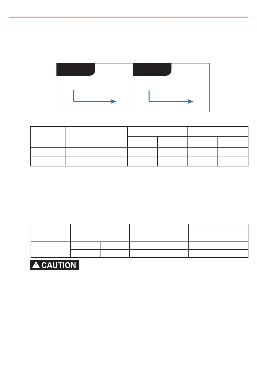
2.3 Input Trigger Settings (BLUE Wire)
The BLUE wire is used to switch the vehicle input turn ON trigger mode between:
• Standard trigger (for fixed voltage or temperature compensating alternators)
• Low Voltage trigger (for variable voltage alternators)
Standard Low Voltage
Vehicle
Ignition
Blue Wire
Not
Connected
Blue Wire
Figure 2.3.1 - Setting the Input Trigger Settings
Input Mode Blue Wire Connection
12V Mode 24V Mode
ON above OFF below ON above OFF below
Standard Not Connected 13.2V 12.7V 26.4V 25.4V
Low Voltage Vehicle Ignition 12.0V 11.9V 24.0V 23.8V
2.4 Cable sizing
Below is a table outlining the required cable size for a given cable install length.
Please refer to this table for Vehicle Input, Solar Input, Ground and Battery Output
cable thickness requirements. Always choose a wire cross sectional area equal
to or greater than what is specied below.
Part Number Cable Install Length
(m) (ft)
Recommended Wire
Cross Section (mm²)
Closest
(BAE, B&S, AWG)
BCDC1250D
1 - 5 3 - 16 13.56 6
5 - 9 16 - 30 20.28 4
Cable and fuse sizes are specied by various codes and standards which depend on the
type of vehicle the Battery Charger is installed into. Selecting the wrong cable or fuse
size could result in harm to the installer or user and/or damage to the Battery Charger or
other equipment installed in the system. The installer is responsible for ensuring that the
correct cable and fuse sizes are used when installing this Battery Charger.
Cabling is recommended to be away from heat sources and in protected areas,
especially when installing or routing in engine bay.

 Loading...