E1/E20/E2/E2 Lite Additional Document 2. Designing the User System
R20UT1994EJ0900 Rev.9.00 Page
of 58
Jan.20.22
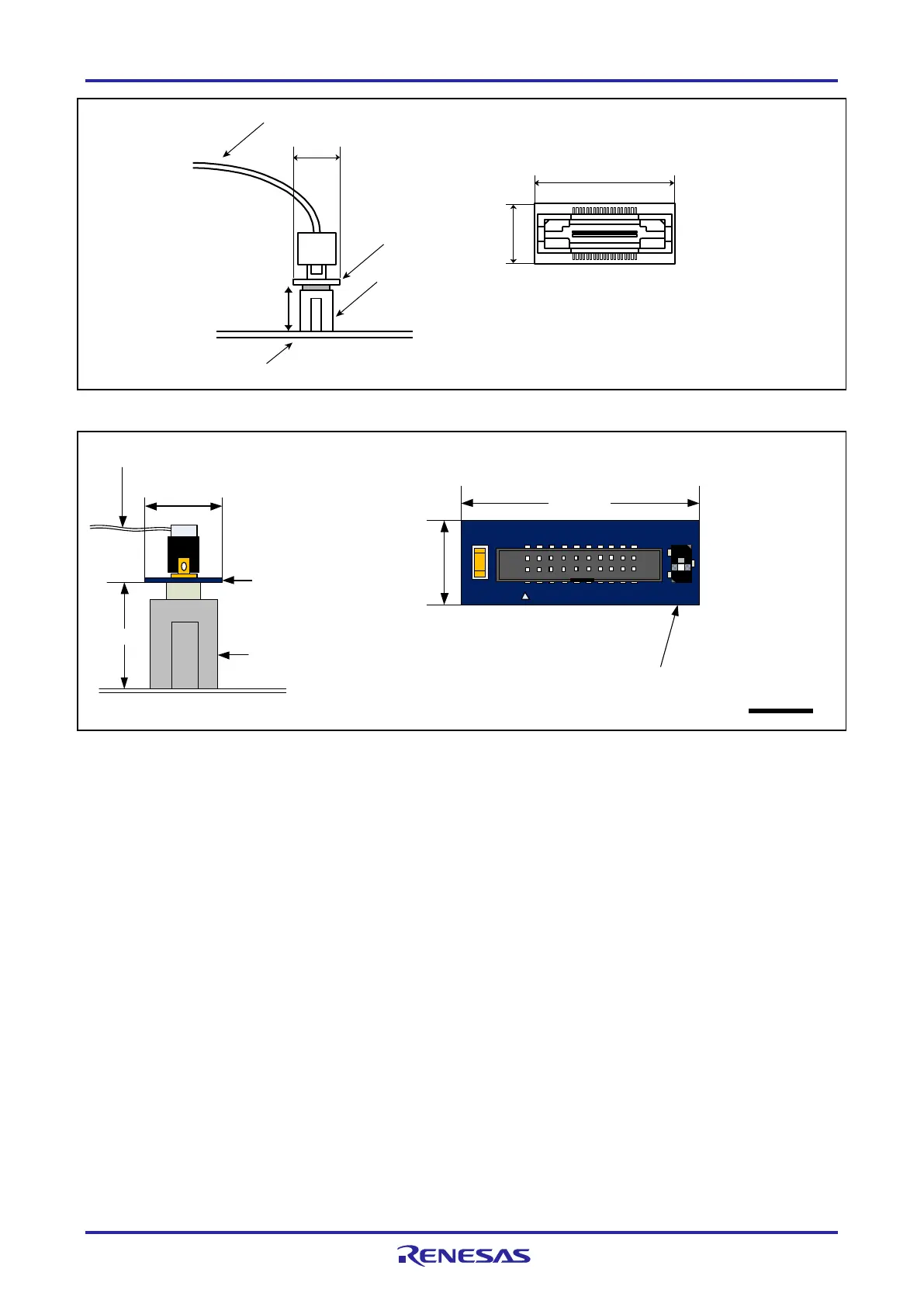
Figure 2-2 Connecting the User System Interface Cable to the 14-Pin Connector of the E20 Emulator
20-pin (1.27-mm pin spacing) user-system
interface cable
13 mm
10.5 mm
User system
14-pin (2.54-mm pin spacing)
connector
7614-6002 or 2514-6002
20-pin (1.27-mm pin
spacing) to 14-pin
(2.54-mm pin spacing)
connector conversion
adapter
10.5 mm
20-pin (1.27-mm pin spacing) to 14-pin
(2.54-mm pin spacing) connector
conversion adapter (top view)
29.0 mm
1
3
Set the switch to position "3".
Figure 2-3 Connecting the User System Interface Cable to the 14-Pin Connector of the E2 Emulator
38-pin to 14-pin conversion adapter (top view)
R0E000200CKA00
(include in the E20 package)
10 mm
User system
38-pin user-system interface cable
26.2 mm
9.4 mm
38-pin to 14-pin
conversion adapter
9.4 mm
14-pin connector
7614-6002 or
2514-6002

 Loading...


