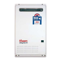
Anti-Frost Heater Circuit
Models with an „F‟ in the model number have an anti frost heater circuit e.g. 871024NF-B.
The anti-frost heaters are wired in series and operate independently from the water heater.
The 18 and 20 litre models have a 58-watt anti-frost system. The 24 and 26 litre models
have an 82-watt anti-frost system.
A thermostat sensing ambient air temperature, positioned in the wiring loom near the
bottom of the water heater, activates the anti-frost heaters when the ambient air
temperature falls to 4ºC +4ºC/-2ºC and deactivates the anti-frost heaters when the
temperature rises above 12ºC.
In the event a heater block becomes open circuit the total heater circuit is rendered
inoperable. The total heater circuit measures 993.2 ohms for the 18 and 20 litre models.
The total heater circuit measures 702.6 ohms for the 24 and 26 litre models.
The circuit is split into two sections with 4 heaters in total. To determine which section has
failed, isolate the power to the water heater and unplug the wiring connectors at the
thermostat, cord set and the water body assembly heater block. The heat exchanger and
hot water outlet heater‟s resistance (3 heater blocks) is 719.2 ohms for the 18 and 20 litre
models and 565.5 ohms for the 24 and 26 litre models. The resistance of the water body
assembly heater is 274 ohms for the 18 and 20 litre models. The resistance of the water
body assembly heater is 137.1 ohms for the 24 and 26 litre models. Refer to Procedure 10
on page 55 for replacement procedure.
Product Changes
Software Changes
18 and 20 litre models manufactured after July 2006 and 24 and 26 litre models
manufactured after May 2006 have a change to the software which controls the operation
of the heater. When an inlet water temperature of more than 58ºC and more than the set
point temperature minus 2ºC is detected by the inlet water temperature thermistor, the fan
and burner will not operate.
This function has been introduced to enhance the operation of the water heater and
remove the need for a Solar Bypass Valve when the Integrity is connected as an in-series
gas booster to a solar water heating system (for more information refer to „In-series Gas
Boosting‟ on page 15).
Models with the revised software have a –B or -C suffix added to the model number i.e.
817020NF-B or 871024NF-C.
Parts Replacement & Wiring Changes for 871024, 871024-B & 817026 Model Heaters
Only
Some parts for 871024, 871024-B & 871026 model heaters have been superseded and
are no longer available (refer to following tables). If any of these superseded parts are
found to be faulty they must be replaced with current parts available for 871024-C and
871026-B model heaters.
Some current parts utilise different wiring connectors/connections necessitating the
replacement of other interconnecting components when installed in 871024, 871024-B and
871026 model heaters (refer to „Parts Replacement Scenarios‟ on page 11). Part numbers
shown in the following tables which are not marked with an asterisk (*) can be considered
a direct replacement and require no additional components or modifications when installed
in 871024, 871024-B and 871026 model heaters.

 Loading...