TM031 Integrity 18, 20, 24, 26L Service Instructions REV: B
D.O.I: February 2008
This document is stored and maintained electronically by Service. All printed copies not bearing this statement in RED are deemed “uncontrolled”
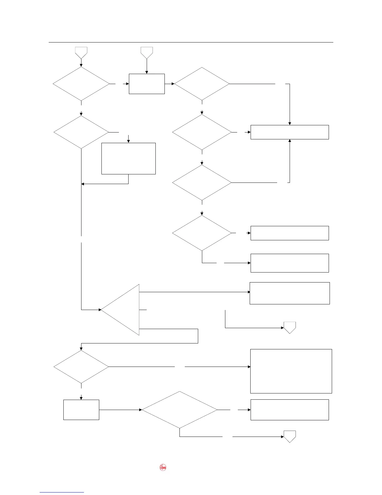
1y = Water flow
detected by water
flow sensor
4
Test 28
Is the
Integrity used as
an in-series gas
booster?
NO
Is the water
flow more than 3
litres/min?
Read
maintenance
information 1y
YES
NO
Is the
voltage between
connector B10 & 11
normal?
Replace the PCB assembly.NO
Is the
voltage between
connector B9 & 10
normal?
YES
YES
Replace the water flow sensor. If
the fault persists replace the
water body assembly.
NO
Are
Controllers
fitted?
YES
Controllers must not be
fitted when an Integrity
is used as an in-series
gas booster. Remove
controllers.
YES
Test 29
NO
Is a
solar bypass valve
fitted?
871024-C models do not require a
solar bypass valve. Remove the
solar bypass valve and remake
water connections directly to
Integrity.
YES
871024-C
NO
Water will flow straight through
the Integrity and the Integrity will
not operate. Normal operation.
Is the
water entering
the Integrity < or = 58ºC or
< or = the set temp
- 2ºC?
NO
4.1
YES
4.1
Read
maintenance
information 3y
3y = Water temp
detected by water
inlet thermistor
871024 or 871024-B
875024-B or 875024-C
875024-B & 875024-C models are
not suitable for use as in-series
gas boosters.
4.2
What is the
model
number?
Is the
flow sensor turbine
jammed?
NO
Test 33
Free the flow sensor turbine.YES
871026-B & 871024-C models
do not require a solar bypass
valve. Remove the solar
bypass valve and remake water
connections directly to Integrity
 Loading...