TM031 Integrity 18, 20, 24, 26L Service Instructions REV: B
D.O.I: February 2008
This document is stored and maintained electronically by Service. All printed copies not bearing this statement in RED are deemed “uncontrolled”
Fault Finding Tests 14 – 22
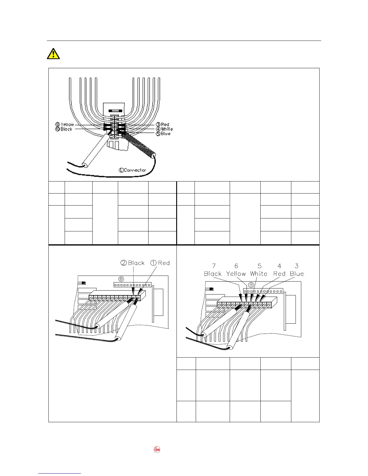
Isolate power when conducting resistance tests. “Live” components present
during voltage tests, exercise caution.
Tests 14, 15, 18, 19, 20 and 21
NOTE:
Measure the voltage with connector L
plugged into PCB
Measure the resistance with connector L
unplugged from the PCB
0.8kilo-ohms
to
2.2kilo-ohms
Tests 16 and 17 - Diagnostic Point 10
Test 22 – Diagnostic Points 6 and 7
Test 16 – Conduct test with water flowing
Measure the voltage with connector B
plugged into PCB. Normal voltage is
between DC1.5 and 8.0V.
Test 17 – Isolate power before conducting
test.
Measure the resistance with connector B
unplugged from the PCB. Normal resistance
is between 42 ohms and 97 ohms.
4y:
Combustion
Chamber
Thermistor
@20ºC –
10.3 kilo-
ohms
@40ºC –
4.9 kilo-
ohms
5y: Hot
Water Outlet
Thermistor
 Loading...