12
(Typical outdoor slab installation is
shown in Figure 9.)
1. Select a location where external
water drainage cannot collect around
unit.
2. Provide a level slab sufficiently high
enough above grade to prevent
surface water from entering the unit
3. Locate the unit to provide proper
access for inspection and servicing
as shown in Figure 12.
4. Locate unit where operating sounds
will not disturb owner or neighbors.
5. Locate unit so roof runoff water does
not pour directly on the unit. Provide
gutter or other shielding at roof level.
Do not locate unit in an area where
excessive snow drifting may occur or
accumulate.
6. Where snowfall is anticipated, the
height of the unit above the ground
level must be considered. Mount unit
high enough to be above anticipated
maximum area snowfall and to allow
combustion air to enter the
combustion air inlet.
7. Select an area which will keep the
areas of the vent, air intake, and A/C
condenser fins free and clear of
obstructions such as weeds, shrubs,
vines, snow, etc. Inform the user
accordingly.
C. ATTACHING EXHAUST AND
COMBUSTION AIR INLET
HOODS
IMPORTANT: Do not operate this unit
without the exhaust/combustion air inlet
hood properly installed. These hoods
are shipped in cartons in the blower
compartment inside the unit and must
be attached when the unit is installed.
See Figure 4.
To attach exhaust/combustion air inlet
hood:
1. Remove screws securing blower
access panel and remove access
panel. For location of blower access
panel, see Figure 3.
2. Remove exhaust/combustion air inlet
hoods from the cartons, located inside
the blower compartment.
3. Attach blower access panel.
4. Attach the combustion air inlet/exhaust
hoods with screws. Reference Figure 4
for proper location. Screws are in
carton with the hood.
5. Vent the unit using the flue exhaust
hood, as supplied from the factory,
without alteration or addition. The only
exception is with factory approved
additions.
D.
COVER PANEL
INSTALLATION/
CONVERSION PROCEDURE
DOWNFLOW TO HORIZONTAL
1. Remove the screws and covers from
the outside of the supply and return
sections. Also remove and discard
cover plate. See Figure 7.
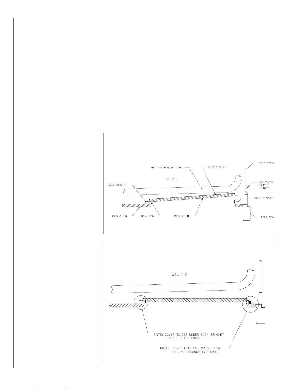
2. Install the covers over the bottom
supply and return openings, painted
side up, inserting the leading flange
under the bracket provided. Place
the back flange to top of the front
bracket provided. See Figures 10
and 11.
3. Secure the return and supply cover to
front bracket with two (2) screws.
E.
FILTER REPLACEMENT
This unit is provided with 3 - 18” X 18” X 2”
and 3 - 18” X 24” X 2” disposable filters.
When replacing filters, ensure they are
inserted fully to the back to prevent
bypass. See Figure 5.
Recommended supplier of this filter is
Glassfloss Industries, Inc. or
AAF International
215 Central Avenue
P.O. Box 35690
Louisville, KY 40232
Phone: 1-800-501-3146
Part #: 54-42541-01 (18" x 18" x 2")
54-42541-03 (18" x 24" x 2")
FIGURE 10. HORIZONTAL
CONVERSION DETAIL
ST-A0886-30
FIGURE 11. HORIZONTAL
CONVERSION DETAIL
ST-A0886-31
 Loading...