21
V. FURNACE SECTION CONTROLS AND IGNITION SYSTEM
thermostat input. If only W1 is called
for, W2 is de-energized and the
control starts a 30 second off delay on
the W2 inducer(s).
11. After fixed 30 seconds the W2
inducers is de-energized.
12. Control enters normal operating loop
where all inputs are continuously
checked.
13. Zone thermostat is satisfied.
14. Control de-energizes gas valve.
15. Control senses loss of flame.
16. Control initiates 5 second inducer
postpurge and 90 second indoor
blower delay off.
17. Control de-energizes inducer
blower(s).
18. Control de-energizes indoor blower.
19. Control in the stand by mode with
solid red LED.
B. Call For Second Stage,
After First
Stage Established; Starting from A.11:
1. If a call for second stage (high fire) is
initiated after a call for first stage heat
is established, the control verifies W2
pressure switches for normally open
contacts. The control energizes the
W2 inducers and energizes the
second stage of the gas valve.
2. Control enters normal operating loop
where all inputs are continuously
checked.
C. Second Stage Satisfied; First Stage
Still Called For; Starting From B.3:
1. Once the call for second stage is
satisfied, the control starts a 30
second off delay on W2 inducers and
reduces the gas valve to first stage.
2. Control enters normal operating loop
where all inputs are continuously
checked.
D. First Stage Satisfied:
1. Zone thermostat is satisfied.
2. Control de-energizes gas valve.
3. Control senses loss of flame.
4. Control initiates 5 second inducer
postpurge and 90 second indoor
blower delay off.
5. Control de-energizes inducer blower.
6. Control de-energizes indoor blower.
7. Control in the stand by mode with solid
red LED.
E. First Stage and Second Stage Called
Simultaneously:
1. Zone thermostat contacts close, a call
for first stage (low fire) and second
stage (high fire) heat is initiated.
2. Control runs self check.
3. Control checks the high-limit switch for
normally closed contacts, each
pressure switch for normally open
contacts, and all flame rollout switches
for continuity.
4. Control energizes each inducer.
5. Control checks each pressure switch
for closure.
6. If each pressure switch is closed, the
control starts a 30 second prepurge
and energizes W2. If either switch is
still open, the inducers will continue to
be energized until closure.
7. After prepurge timeout, control
energizes W1 and continues to
energize W2, initiates spark for 2
seconds minimum, 7 second maximum
ignition trial, and initiates 120 second
stage warm up timing.
8. Control detects flame, de-energizes
spark and starts a 45 second indoor
blower delay on timing.
9. After a fixed 45 seconds indoor blower
delay on, the control energizes the
indoor blower.
10. After a fixed 120 seconds second stage
warmup period control checks the
thermostat input. If W1 and W2 is
present control enters normal operating
loop where all inputs are continuously
checked.
F. First Stage and Second Stage
Removed Simultaneously:
1. Upon a loss of W1 and W2 the gas
valve is de-energized.
2. Upon a loss of flame, each inducer will
complete a 5 second postpurge and
the indoor blower will complete a 90
second delay off.
3. Control in the stand by mode with solid
red LED.
The integrated control is a three ignition
system.
After a total of three cycles without sensing
main burner flame, the system goes into a
100% lockout mode. After one hour, the
ignition control repeats the prepurge and
ignition cycles for 3 tries and then goes into
100% lockout mode again. It continues this
sequence of cycles and lockout each hour
until ignition is successful or power is
interrupted. During the lockout mode,
neither the ignitor or gas valve will be
energized until the system is reset by
turning the thermostat to the “OFF” position
or interrupting the electrical power to the
unit for 3 seconds or longer.
The circulating air blower will start and run
on the heating speed if the thermostat fan
switch is in the “ON” position.
NORMAL FURNACE
OPERATING SEQUENCE
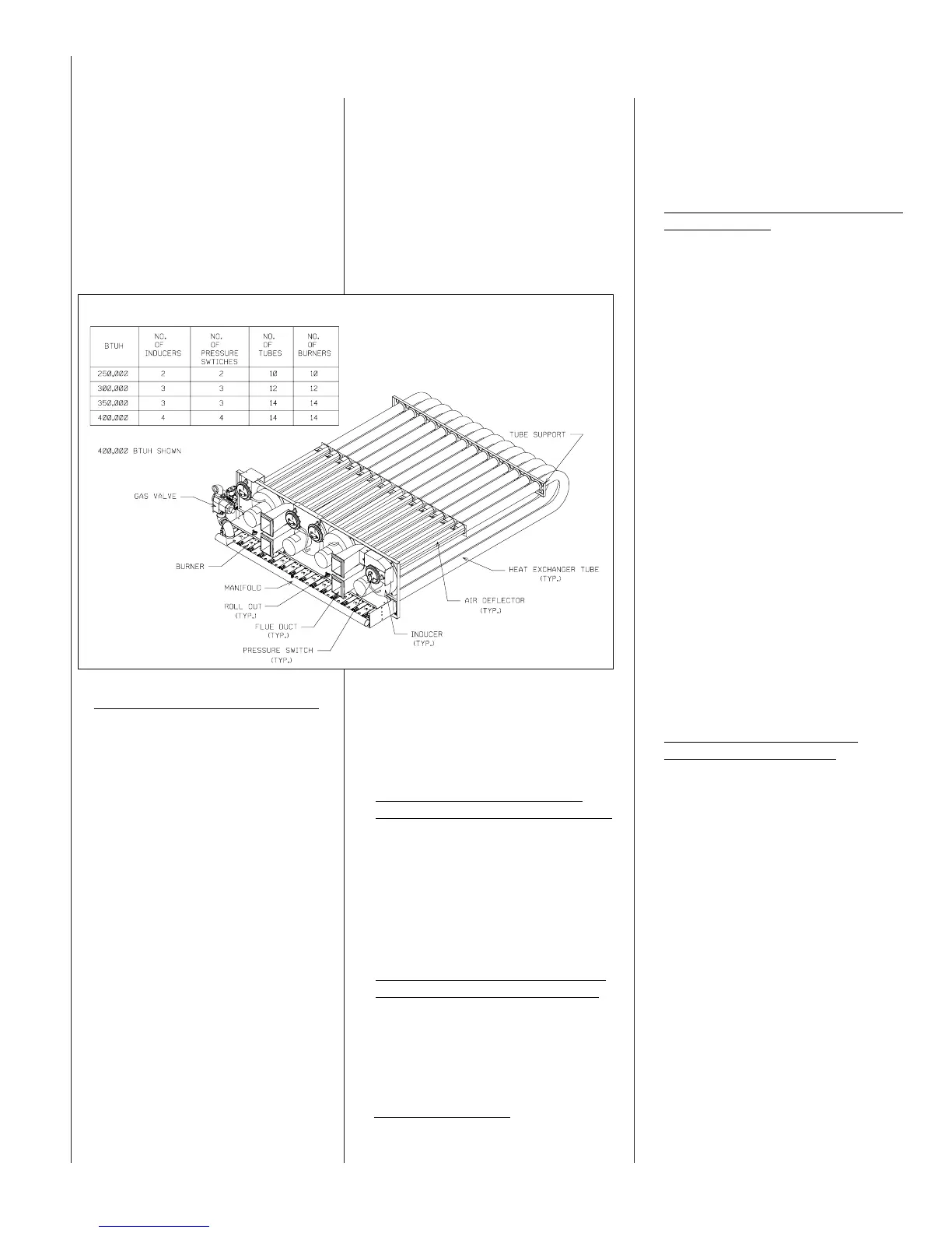
This unit has a two stage gas furnace
which employs an integrated furnace
control with self diagnostics located in the
control box. The furnace is composed of
induced draft blowers, negative pressures
switches, two stage gas valve, manifold
orifices, inshot burners, direct spark
ignitor, remote flame sense, tubular heat
exchanger, high limit switch and rollout
switches. See Figure 23.
NORMAL HEAT MODE
A. Call For First Stage (low fire) Only:
1. Zone thermostat contacts close, a call
for first stage (low fire) heat is
initiated.
2. Control runs self check.
3. Control checks the high-limit switch
for normally closed contacts, each
pressure switch for normally open
contacts, and all flame rollout
switches for continuity.
4. Control energizes each inducer.
5. Control checks each pressure switch
for closure.
6. If each pressure switch is closed, the
control starts a 30 second prepurge
and energizes W2. If any pressure
switch is still open, the inducers will
continue to be energized until closure.
7. After prepurge timeout, control
energizes W1 and continues to
energize W2, initiates spark for 2
seconds minimum, 7 second
maximum ignition trial, initiates 120
second, second stage (high fire)
warm up timing.
8. Control detects flame, de-energizes
spark and initiates 45 second delay
on blower timing.
9. After a fixed 45 seconds indoor
blower delay on, the control energizes
the indoor blower.
10. After a fixed 120 seconds second
stage warmup period control checks
FIGURE 23.
ST-A0886-29
 Loading...