12.2 Comfort Control
2
System™ Control Wiring
An HVAC system equipped with Comfort Control
2
System™ consists of:
• Heat pump or condensing unit equipped with Comfort Control
2
• Air handler or furnace equipped with Comfort Control
2
• Comfort Control
2
thermostat
The four 18AWG low voltage control wires must be installed from the thermostat to
the indoor unit and from indoor unit to the outdoor unit. The wire length between the
thermostat and indoor unit should not be greater than 100 feet. The wire length
between the indoor unit and outdoor unit should not be greater than 125 feet.
IIMMPPOORRTTAANNTT::
If the installed system does not meet these requirements, the sys-
tem must be wired using traditional control wiring, reference Section 12.7
Conventional 24VAC Thermostat Control Wiring.
Serial communications require four (4) control wires for unit operation:
R – 24VAC
C – 24VAC common
1 – Data wire 1
2 – Data wire 2
NNoottee::
Comfort Control
2
System™ requires 18 AWG thermostat wire.
NNoottee::
TERM dipswitches should be in ON position.
If the low voltage control wiring is run in conduit with the power supply, Class I insu-
lation is required. Class II insulation is required if run separate. Low voltage wiring
may be run through the insulated bushing provided in the 7/8 hole in the base
panel, up to and attached to the pigtails from the bottom of the control box. Conduit
can be run to the base panel if desired by removing the insulated bushing.
The serial communicating air handler or serial communicating furnace transformer
is equipped with a 24 volt, 50 VA transformer for proper system operation. See the
wiring diagram in Figure 5 for reference.
12.3 Comfort Control
2
System™ Diagnostic Codes in Dual Drive
12.3 Condensing Units
Comfort Control
2
System™ controls for both compressors are connected to the ser-
ial communicating network via Data Wire 1 and Data Wire 2. Each Comfort Control
2
System™ control board maintains separate fault history for the compressor it con-
trols. Fault codes for both compressors can be retrieved using a service tool or via
the installer menus.
COMFORT CONTROL
2
SYSTEM™ CONTROL WIRING
20
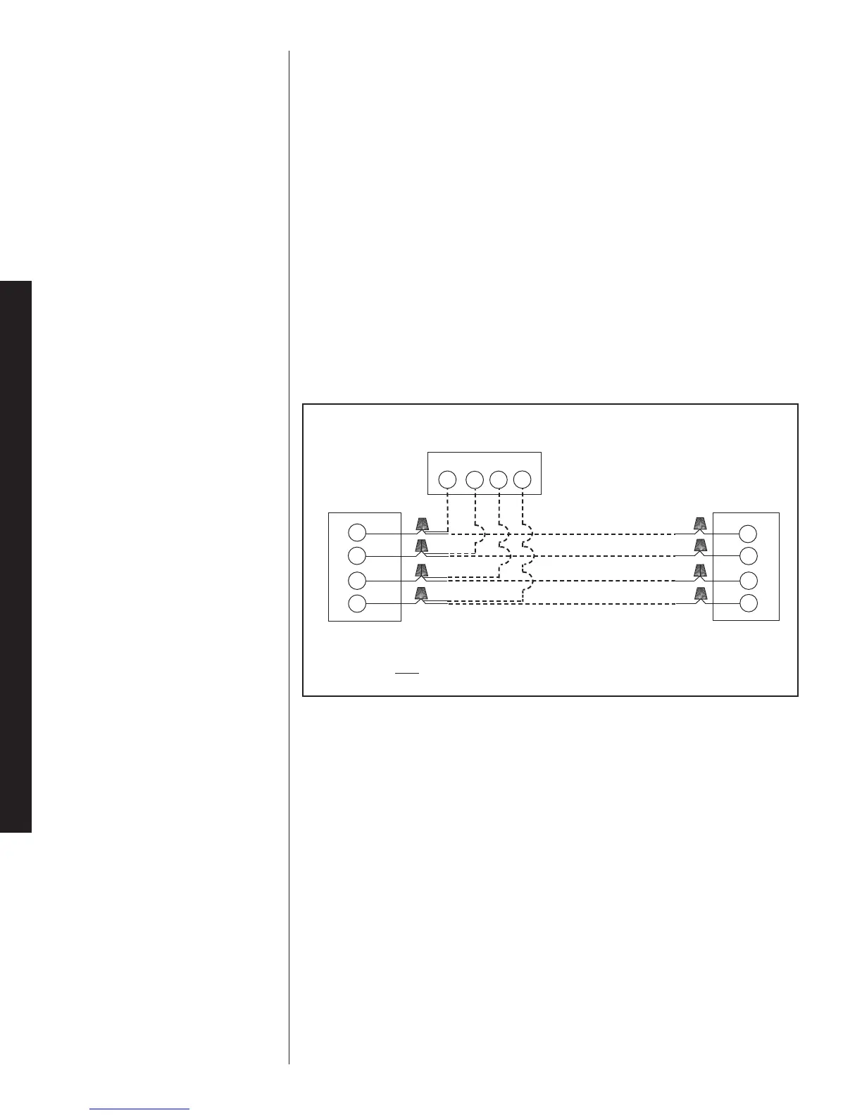
FIGURE 7
TYPICAL COMFORT CONTROL
2
SYSTEM™ WIRING DIAGRAM
Indoor Unit
1
2
C
R
WIRING INFORMATION
Line Voltage
–Field Installed - - - - - -
–Factory Standard
1
2
R
C
1
2
R
C
Communicating Thermostat
Outdoor Unit
 Loading...