26
ICC Diagnostic Codes
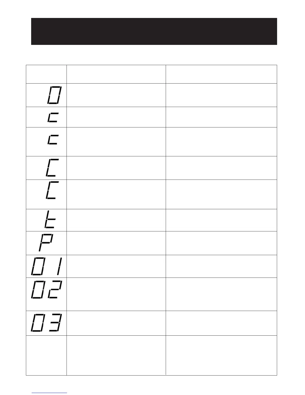
Descriptions of the ICC diagnostic codes are provided below:
12.7
COMFORT CONTROL
2
SYSTEM™ CONTROL WIRING
AND
CONVENTIONAL THERMOSTAT WIRING
ICC DIAGNOSTIC CODES
Dual 7-Segment
LEDs Display
Code
Diagnostic Description
0 – Standby
No command for unit operation
Normal operation
c - First Stage Cooling
Unit has received a command for first stage
cooling
Normal operation
c - Anti-short cycle timer (3 minutes) or
Minimum run timer (30 seconds) active
• The unit has received a command for first stage
cooling during an active anti-short cycle timer
or minimum run timer.
• Wait until unit timer has expired or press the
TEST button to defeat short cycle delay.
C - Second Stage Cooling
Unit has received a command for second
stage cooling
Normal operation
C - Anti-short cycle timer (3 minutes) or
Minimum run timer (30 seconds) active
• The unit has received a command for second
stage cooling during an active anti-short cycle
timer or minimum run timer.
• Wait unit timer has expired or press the TEST
button to defeat short cycle delay.
Status/Possible Cause – Troubleshooting
Information
10
13.X ICC Diagnostic Codes
Descriptions of the ICC diagnostic codes are provided below:
7-Segment
LEDs Display
Code Diagnostic Description
Status/Possible Cause – Troubleshooting
Information
0 – Standby
No command for unit operation
Normal operation
c - First Stage Cooling
Unit has received a command for first stage
cooling
Normal operation
FLASHING
c - Anti-short cycle timer (3 minutes) or
Minimum run timer (30 seconds) active
• The unit has received a command for first stage
cooling during an active anti-short cycle timer
or minimum run timer.
• Wait until unit timer has expired or press the
TEST button to reset timer.
C - Second Stage Cooling
Unit has received a command for second
stage cooling
Normal operation
FLASHING
C - Anti-short cycle timer (3 minutes) or
Minimum run timer (30 seconds) active
• The unit has received a command for second
stage cooling during an active anti-short cycle
timer or minimum run timer.
• Wait unit timer has expired or press the TEST
button to reset timer.
h1 - First Stage Heat Pump
Unit has received a command for first stage
heat pump
Normal operation
FLASHING
h1 - Anti-short cycle timer (3 minutes) or
Minimum run timer (30 seconds) active
• The unit has received a command for first stage
heat pump during an active anti-short cycle
timer or minimum run timer.
• Wait unit timer has expired or press the TEST
button to reset timer.
h2 - Second Stage Heat Pump
Unit has received a command for second
stage heat pump
Normal operation
FLASHING
h2 - Anti-short cycle timer (3 minutes) or
Minimum run timer (30 seconds) active
• The unit has received a command for second
stage heat pump during an active anti-short
cycle timer or minimum run timer.
• Wait unit timer has expired or press the TEST
button to reset timer.
d - Defrost Active
The unit is undergoing a defrost cycle
Normal operation
t - Test Mode The ICC is in TEST mode
t - Test Mode The ICC is in TEST mode
10
1
3.X ICC Diagnostic Codes
Descriptions of the ICC diagnostic codes are provided below:
7-Segment
L
EDs Display
Code Diagnostic Description
S
tatus/Possible Cause – Troubleshooting
Information
0 – Standby
N
o command for unit operation
Normal operation
c
- First Stage Cooling
Unit has received a command for first stage
c
ooling
N
ormal operation
FLASHING
c - Anti-short cycle timer (3 minutes) or
Minimum run timer (30 seconds) active
• The unit has received a command for first stage
cooling during an active anti-short cycle timer
o
r minimum run timer.
• Wait until unit timer has expired or press the
T
EST button to reset timer.
C - Second Stage Cooling
Unit has received a command for second
stage cooling
N
ormal operation
FLASHING
C - Anti-short cycle timer (3 minutes) or
M
inimum run timer (30 seconds) active
•
The unit has received a command for second
stage cooling during an active anti-short cycle
timer or minimum run timer.
• Wait unit timer has expired or press the TEST
button to reset timer.
h1 - First Stage Heat Pump
Unit has received a command for first stage
heat pump
Normal operation
FLASHING
h1 - Anti-short cycle timer (3 minutes) or
Minimum run timer (30 seconds) active
• The unit has received a command for first stage
heat pump during an active anti-short cycle
timer or minimum run timer.
• Wait unit timer has expired or press the TEST
button to reset timer.
h2 - Second Stage Heat Pump
Unit has received a command for second
stage heat pump
Normal operation
FLASHING
h2 - Anti-short cycle timer (3 minutes) or
Minimum run timer (30 seconds) active
• The unit has received a command for second
stage heat pump during an active anti-short
cycle timer or minimum run timer.
• Wait unit timer has expired or press the TEST
button to reset timer.
d - Defrost Active
The unit is undergoing a defrost cycle
Normal operation
t - Test Mode The ICC is in TEST mode
10
13.X ICC Diagnostic Codes
Descriptions of the ICC diagnostic codes are provided below:
7-Segment
LEDs Display
Code Diagnostic Description
Status/Possible Cause – Troubleshooting
Information
0 – Standby
No command for unit operation
Normal operation
c - First Stage Cooling
Unit has received a command for first stage
cooling
Normal operation
FLASHING
c - Anti-short cycle timer (3 minutes) or
Minimum run timer (30 seconds) active
• The unit has received a command for first stage
cooling during an active anti-short cycle timer
or minimum run timer.
• Wait until unit timer has expired or press the
TEST button to reset timer.
C - Second Stage Cooling
Unit has received a command for second
stage cooling
Normal operation
FLASHING
C - Anti-short cycle timer (3 minutes) or
Minimum run timer (30 seconds) active
• The unit has received a command for second
stage cooling during an active anti-short cycle
timer or minimum run timer.
• Wait unit timer has expired or press the TEST
button to reset timer.
h1 - First Stage Heat Pump
Unit has received a command for first stage
heat pump
Normal operation
FLASHING
h1 - Anti-short cycle timer (3 minutes) or
Minimum run timer (30 seconds) active
• The unit has received a command for first stage
heat pump during an active anti-short cycle
timer or minimum run timer.
• Wait unit timer has expired or press the TEST
button to reset timer.
h2 - Second Stage Heat Pump
Unit has received a command for second
stage heat pump
Normal operation
FLASHING
h2 - Anti-short cycle timer (3 minutes) or
Minimum run timer (30 seconds) active
• The unit has received a command for second
stage heat pump during an active anti-short
cycle timer or minimum run timer.
• Wait unit timer has expired or press the TEST
button to reset timer.
d - Defrost Active
The unit is undergoing a defrost cycle
Normal operation
t - Test Mode The ICC is in TEST mode
P – Protector Trip
A command for compressor operation is
present but no current is measured to the
compressor
• Motor protector open
• Line voltage disconnected
11
d1 – No Shared Data
ELECTRONICS GROUP TO
DESCRIBE
d3 – Airflow CFM Mismatch
The indoor air mover (air handler/furnace)
cannot supply the required airflow for
proper system operation
• Misapplied/wrong indoor air mover – replace
with properly sized air handler/furnace.
P – Protector Trip
A command for compressor operation is
present but no current is measured to the
compressor
• Motor protector open
• Line voltage disconnected
01 – Long Run Time (Compressor)
The compressor has continuously run for
more than 18 hours in the cooling mode.
• Low refrigerant charge
• Air ducts have substantial leakage
• Dirty indoor air filter
• Dirty outdoor coil
02 – High Pressure Control Open
The ICC detects the HPC is open.
Reference ICC codes:
• 21
• L21
• 29
• L29
03 – Short Cycling
The ICC detects the run time for the past
four (4) compressor cycles is less than three
(3) minutes each.
• Check thermostat wire connections (R, C, 1, &
2)
• Check thermostat location in zone (too close to
discharge grill)
L4 – Locked Rotor
The ICC detects four (4) consecutive
protector trips have occurred and the
average run time for each trip is less than 15
seconds
• Bad run capacitor
• Low line voltage
• Excessive refrigerant in compressor
• Seized bearings in compressor
05 – Open Circuit (Compressor will not
Run)
• The ICC has received a command for
unit operation but no current is present in
the start and run circuits.
• The ICC will attempt to restart the unit
every five (5) minutes for four (4)
attempts. After that, the ICC will attempt
a restart every twenty (20) minutes for up
to four (4) hours.
• Check for damaged, miswired, or wrong run
capacitor
• Check for broken wires, loose connectors, or
miswired compressor
• Check compressor windings for continuity
• Check for open compressor internal protector
06 – Compressor Open Start Circuit
The ICC detects current in the Run circuit
but not in the Start circuit of the compressor
• Check for damaged, miswired, or wrong run
capacitor
• Check for broken wires, loose connectors, or
miswired compressor
• Check compressor windings for continuity
07 – Compressor Open Run Circuit
The ICC detects current in the Start circuit
but not in the Run circuit of the compressor
• Check for damaged, miswired, or wrong run
capacitor
• Check for broken wires, loose connectors, or
miswired compressor
• Check compressor windings for continuity
09 – Low Secondary Volts
The secondary voltage at R and C is below
18VAC
• Control transformer overloaded
• Low line voltage
01 – Long Run Time (Compressor)
The compressor has continuously run for
more than 18 hours in the cooling mode.
• Low refrigerant charge
• Air ducts have substantial leakage
• Dirty indoor air filter
• Dirty outdoor coil
11
d1 – No Shared Data
ELECTRONICS GROUP TO
DESCRIBE
d3 – Airflow CFM Mismatch
The indoor air mover (air handler/furnace)
cannot supply the required airflow for
proper system operation
• Misapplied/wrong indoor air mover – replace
with properly sized air handler/furnace.
P – Protector Trip
A command for compressor operation is
present but no current is measured to the
compressor
• Motor protector open
• Line voltage disconnected
01 – Long Run Time (Compressor)
The compressor has continuously run for
more than 18 hours in the cooling mode.
• Low refrigerant charge
• Air ducts have substantial leakage
• Dirty indoor air filter
• Dirty outdoor coil
02 – High Pressure Control Open
The ICC detects the HPC is open.
Reference ICC codes:
• 21
• L21
• 29
• L29
03 – Short Cycling
The ICC detects the run time for the past
four (4) compressor cycles is less than three
(3) minutes each.
• Check thermostat wire connections (R, C, 1, &
2)
• Check thermostat location in zone (too close to
discharge grill)
L4 – Locked Rotor
The ICC detects four (4) consecutive
protector trips have occurred and the
average run time for each trip is less than 15
seconds
• Bad run capacitor
• Low line voltage
• Excessive refrigerant in compressor
• Seized bearings in compressor
05 – Open Circuit (Compressor will not
Run)
• The ICC has received a command for
unit operation but no current is present in
the start and run circuits.
• The ICC will attempt to restart the unit
every five (5) minutes for four (4)
attempts. After that, the ICC will attempt
a restart every twenty (20) minutes for up
to four (4) hours.
• Check for damaged, miswired, or wrong run
capacitor
• Check for broken wires, loose connectors, or
miswired compressor
• Check compressor windings for continuity
• Check for open compressor internal protector
06 – Compressor Open Start Circuit
The ICC detects current in the Run circuit
but not in the Start circuit of the compressor
• Check for damaged, miswired, or wrong run
capacitor
• Check for broken wires, loose connectors, or
miswired compressor
• Check compressor windings for continuity
07 – Compressor Open Run Circuit
The ICC detects current in the Start circuit
but not in the Run circuit of the compressor
• Check for damaged, miswired, or wrong run
capacitor
• Check for broken wires, loose connectors, or
miswired compressor
• Check compressor windings for continuity
09 – Low Secondary Volts
The secondary voltage at R and C is below
18VAC
• Control transformer overloaded
• Low line voltage
02 – High Side Fault
Compressor limit has opened four (4) times
within a call for operation
• Outdoor coil is dirty (cooling mode)
• Outdoor fan is not running (cooling mode)
• Dirty indoor coil or filter (heating mode)
• Indoor blower is not running (heating mode)
• Liquid line restriction
• Excessive refrigerant charge
11
d1 – No Shared Data
ELECTRONICS GROUP TO
DESCRIBE
d3 – Airflow CFM Mismatch
The indoor air mover (air handler/furnace)
cannot supply the required airflow for
proper system operation
• Misapplied/wrong indoor air mover – replace
with properly sized air handler/furnace.
P – Protector Trip
A command for compressor operation is
present but no current is measured to the
compressor
• Motor protector open
• Line voltage disconnected
01 – Long Run Time (Compressor)
The compressor has continuously run for
more than 18 hours in the cooling mode.
• Low refrigerant charge
• Air ducts have substantial leakage
• Dirty indoor air filter
• Dirty outdoor coil
02 – High Pressure Control Open
The ICC detects the HPC is open.
Reference ICC codes:
• 21
• L21
• 29
• L29
03 – Short Cycling
The ICC detects the run time for the past
four (4) compressor cycles is less than three
(3) minutes each.
• Check thermostat wire connections (R, C, 1, &
2)
• Check thermostat location in zone (too close to
discharge grill)
L4 – Locked Rotor
The ICC detects four (4) consecutive
protector trips have occurred and the
average run time for each trip is less than 15
seconds
• Bad run capacitor
• Low line voltage
• Excessive refrigerant in compressor
• Seized bearings in compressor
05 – Open Circuit (Compressor will not
Run)
• The ICC has received a command for
unit operation but no current is present in
the start and run circuits.
• The ICC will attempt to restart the unit
every five (5) minutes for four (4)
attempts. After that, the ICC will attempt
a restart every twenty (20) minutes for up
to four (4) hours.
• Check for damaged, miswired, or wrong run
capacitor
• Check for broken wires, loose connectors, or
miswired compressor
• Check compressor windings for continuity
• Check for open compressor internal protector
06 – Compressor Open Start Circuit
The ICC detects current in the Run circuit
but not in the Start circuit of the compressor
• Check for damaged, miswired, or wrong run
capacitor
• Check for broken wires, loose connectors, or
miswired compressor
• Check compressor windings for continuity
07 – Compressor Open Run Circuit
The ICC detects current in the Start circuit
but not in the Run circuit of the compressor
• Check for damaged, miswired, or wrong run
capacitor
• Check for broken wires, loose connectors, or
miswired compressor
• Check compressor windings for continuity
09 – Low Secondary Volts
The secondary voltage at R and C is below
18VAC
• Control transformer overloaded
• Low line voltage
03 – Short Cycling
The ICC detects the run time for the past
four (4) compressor cycles is less than three
(3) minutes each.
• Check thermostat wire connections (R, C, 1, &
2)
• Check thermostat location in zone (too close to
discharge grill)
11
d1 – No Shared Data
ELECTRONICS GROUP TO
DESCRIBE
d3 – Airflow CFM Mismatch
The indoor air mover (air handler/furnace)
cannot supply the required airflow for
proper system operation
• Misapplied/wrong indoor air mover – replace
with properly sized air handler/furnace.
P – Protector Trip
A command for compressor operation is
present but no current is measured to the
compressor
• Motor protector open
• Line voltage disconnected
01 – Long Run Time (Compressor)
The compressor has continuously run for
more than 18 hours in the cooling mode.
• Low refrigerant charge
• Air ducts have substantial leakage
• Dirty indoor air filter
• Dirty outdoor coil
02 – High Pressure Control Open
The ICC detects the HPC is open.
Reference ICC codes:
• 21
• L21
• 29
• L29
03 – Short Cycling
The ICC detects the run time for the past
four (4) compressor cycles is less than three
(3) minutes each.
• Check thermostat wire connections (R, C, 1, &
2)
• Check thermostat location in zone (too close to
discharge grill)
L4 – Locked Rotor
The ICC detects four (4) consecutive
protector trips have occurred and the
average run time for each trip is less than 15
seconds
• Bad run capacitor
• Low line voltage
• Excessive refrigerant in compressor
• Seized bearings in compressor
05 – Open Circuit (Compressor will not
Run)
• The ICC has received a command for
unit operation but no current is present in
the start and run circuits.
• The ICC will attempt to restart the unit
every five (5) minutes for four (4)
attempts. After that, the ICC will attempt
a restart every twenty (20) minutes for up
to four (4) hours.
• Check for damaged, miswired, or wrong run
capacitor
• Check for broken wires, loose connectors, or
miswired compressor
• Check compressor windings for continuity
• Check for open compressor internal protector
06 – Compressor Open Start Circuit
The ICC detects current in the Run circuit
but not in the Start circuit of the compressor
• Check for damaged, miswired, or wrong run
capacitor
• Check for broken wires, loose connectors, or
miswired compressor
• Check compressor windings for continuity
07 – Compressor Open Run Circuit
The ICC detects current in the Start circuit
but not in the Run circuit of the compressor
• Check for damaged, miswired, or wrong run
capacitor
• Check for broken wires, loose connectors, or
miswired compressor
• Check compressor windings for continuity
09 – Low Secondary Volts
The secondary voltage at R and C is below
18VAC
• Control transformer overloaded
• Low line voltage
L4 – Locked Rotor
The ICC detects four (4) consecutive
protector trips have occurred and the run time
before each trip is less than 15 seconds
• Bad run capacitor
• Low line voltage
• Excessive refrigerant in compressor
• Seized bearings in compressor
L
0 7
 Loading...