54
Gas Supply
INSTALLATION INSTRUCTIONS
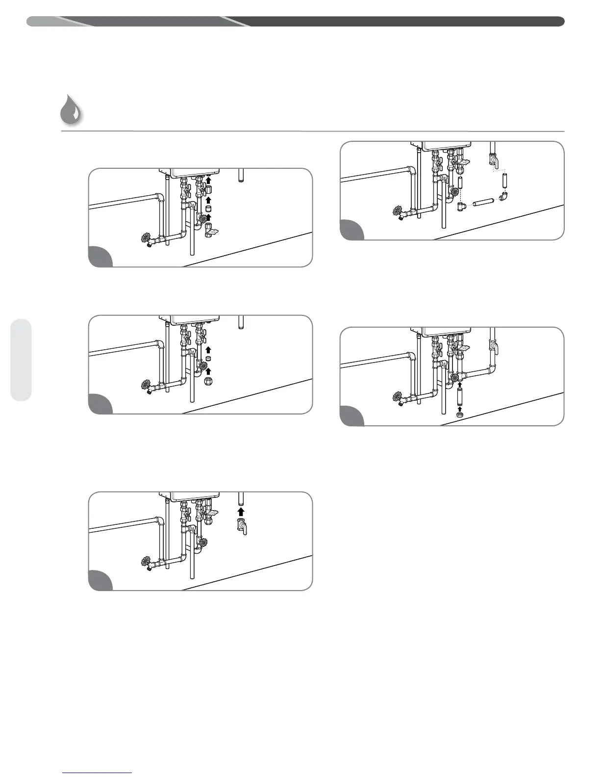
Gas Supply Installation
Install the manual gas appliance shut-off valve to
the gas connection at the water heater. The shut-
off is supplied with the water heater.
Install a ground joint union or ANSI design-certified
semi-rigid or flexible gas appliance connector to
the open end of the manual gas appliance shut-off
valve. The (NFGC) ANSI Z223.1 and CAN/CSA B149.1
codes mandate the use of manual gas shut-off
valve.
Install a manual gas supply line shut-off valve
to the end of the gas supply line.
NOTICE: Lever-type gas shut-offs should all
be T-handle type.
Using the proper-size piping, fittings, and
components, build the gas supply line to the water
heater.
NOTICE: The gas supply line should be a
minimum of 3/4-in. (1.9-cm) black steel pipe or
other approved gas piping material.
Install a sediment trap at the lowest portion of the
gas line.
The inlet gas pressure to the water heater must NOT
exceed 10.5 in. w.c. (2.6 kPa) for natural gas and
14 in. w.c. (3.5 kPa) for LP gas. For purposes of input
adjustment, the minimum inlet gas pressure (with main
burner on) is shown on the water heater rating plate.
If high or low gas pressures are present, contact your
gas supplier for correction.
1
2
4
3
5
Gas Supply (cont.)
 Loading...