3
A B C D E F G
COL
D
(NPT)
HOT
(NPT)
Gas
(NPT)
Air
Intake
(PVC)
Exhaust
Vent
(PVC)
93
2" 2" 1-1/2" 4" 4"
1200 (544)
GHE 125-500A
(146.5)
93
(2,112)
(2,445)
(199)
(81)
(159)
(29)
(24)
(156)
(188)
2" 2" 1-1/2" 4" 4"
1200 (544)
Shipping
Weight,
LBS (kg)
Table 1: Specificaons
NOTE: Suffix "-A" denotes ASME version.
Model
Rated
Storage
Capacity,
GAL (L)
Rated
Maximu
m Input,
Btu/hr
(kW)
Thermal
Efficiency
(%) @
Max.
Input
Recovery
@ 100°F
rise,
GAL/HR
(L/HR)
1st Hr.
Delivery
@ 100°F
rise, GAL
(L)
FOR PROPANE GAS models, suffix will be“LP”
For HIGH ALTITUDE models, the following additional suffixes are
defined as:
HA (Natural Gas) = Approved for altitudes greater than 2,000 up
to 7,800 FT
HA1 (LP Gas)= Approved for altitudes greater than 2,000 up to
5,400 FT
HA2 (LP Gas)= Approved for altitudes greater than 5,400 up to
7,800 FT
(For LP Models see table 6 for approved altitude ranges)
FOR NATURAL GAS:
MINIMUM GAS SUPPLY PRESSURE (at gas control) = 6” W.C. (dynamic)
MAXIMUM GAS SUPPLY PRESSURE (at gas control) = 14” W.C.
(static or dynamic)
FOR LP GAS:
MINIMUM GAS SUPPLY PRESSURE (at gas control) = 8” W.C.
(dynamic)
MAXIMUM GAS SUPPLY PRESSURE (at gas control) = 14” W.C.
(static or dynamic)
Note: Dynamic pressure is measured while gas is flowing and
static pressure is measured while gas is not flowing.
All products meet or exceed current ASHRAE standards.
These products are design certified by UL (Underwriters Labora-
tories) and meet ANSI Z21.10.3/CSA 4.3 requirements for opera-
tion up to 180°F (82°C).
Approved for use as a direct vent automatic storage water heater.
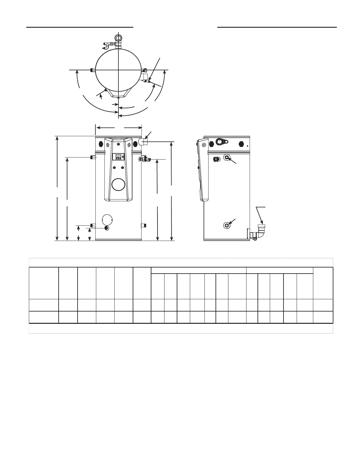
Figure: 1
Specifications
E
D
A
C
HOT
COLD
DRAIN
EXHAUST VENT CONN./
CONDENSATE ASSEMBLY
4" PVC
SIDE VIEW
FRONT VIEW
TOP VIEW
HOT
COLD
F
G
B
HOT
T&P
VALVE
COMBUSTION AIR
INTAKE 4" PVC
90°
68°
90°
30°
HOT/COLD
HOT/COLD
GAS CONN.
T&P VALVE
 Loading...