13
LIGHTING INSTRUCTIONS
This appliance is equipped with an
automatic electronic ignition device.
This device lights the oil burner each
time the room thermostat “closes” calls
for heat. See oil burner instructions
enclosed with furnace for further detail.
MAKE SURE THAT COMBUSTION
CHAMBER IS FREE OF OIL BEFORE
USING RESET BUTTON ON
PRIMARY CONTROL. FAILURE TO
DO SO CAN CAUSE FLASH FIRE OR
EXPLOSION RESULTING IN
PROPERTY DAMAGE, PERSONAL
INJURY OR DEATH.
TO START FURNACE
1. Set room thermostat to highest
setting.
2. Open shut-off valve in oil supply line.
3. Close line switch. Burner should
start automatically.
4. Bleed the fuel pump as soon as the
burner motor starts rotating. To
bleed the fuel unit, attach a clear
plastic hose over the bleed plug.
Loosen the plug and catch the oil in
an empty container. Tighten the plug
when all air is purged. (See section
titled “Oil Pump/Pump” for more
information on bleeding the pump.)
WARNING
!
5. Reset room thermostat to desired
temperature setting.
TO STOP FURNACE
1. Set the room thermostat to lowest
temperature setting.
2. Turn “Off” line switch to the furnace.
IF BURNER DOES NOT START
1. Check fuse or breaker in the furnace
circuit.
2. Assure room thermostat is set above
room temperature.
3. Check oil level in the tank.
4. Make sure that oil line shut-off
valves are open.
5. Wait five minutes to allow the control
to cool, so that it will recycle. Reset
the button on the primary control.
6. Depress manual reset button on the
motor.
NOTE: Do not expose cad cell to
direct electric bulb light or sunlight.
Light may enter through the air control
band slot and upset the electric circuit
of this device.
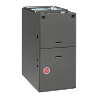
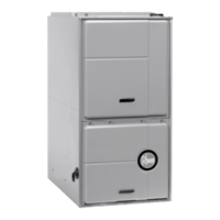
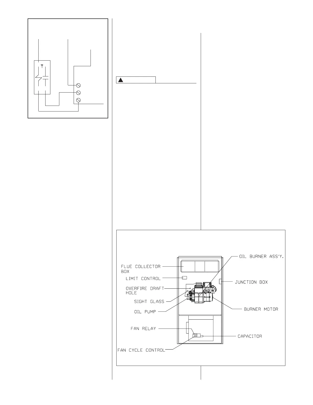
OPERATING INSTRUCTIONS
FIGURE 14
COMPONENT LOCATION
ST-A1066-01
NOTE: Do not use 24-volt control
wiring that is smaller than number 18
AWG. The maximum circuit ampacity
is 1.6. The Heat Anticipator should be
set for 0.10 amps.
NOTE: An isolation relay can be added
to prevent any compatibility problems
that may occur. Use a single-pole,
single-throw relay with 24-volt AC coil.
The contacts should be rated for .5
amps minimum at 24 volts. See Figure
13.
The current ProStock part number is
42-25104-01 for a SPNO Pilot/Power
24 volt relay.
IMPORTANT: Do not use a power-
robbing electronic thermostat with this
furnace. Use only mechanical
thermostats or battery powered
electronic thermostats.
Install the room thermostat in
accordance with the instruction sheet
packed in the box with the thermostat.
Run the thermostat lead wires inside
the blower compartment and connect
to low voltage terminals as shown on
the wiring diagram. Never install the
thermostat on an outside wall or where
it will be influenced by drafts,
concealed hot or cold water pipes or
ducts, lighting fixtures, radiation from
fireplace, sun rays, lamps, televisions,
radios or air streams from registers.
Refer to instructions packed with the
thermostat for “heater” selection or
adjustment.
NOTE: Do not use 24 volt control
wiring smaller than No. 18 AWG.
HEAT ANTICIPATOR
SETTING
The heating thermostat anticipator
should be set for a 0.10 amp draw.
FIGURE 13
ISOLATION RELAY
➁
➂
➀
➃
TO THERMOSTAT
“W” TERMINAL
TO THERMOSTAT
“R” TERMINAL
JUMPER
RWC
 Loading...