28
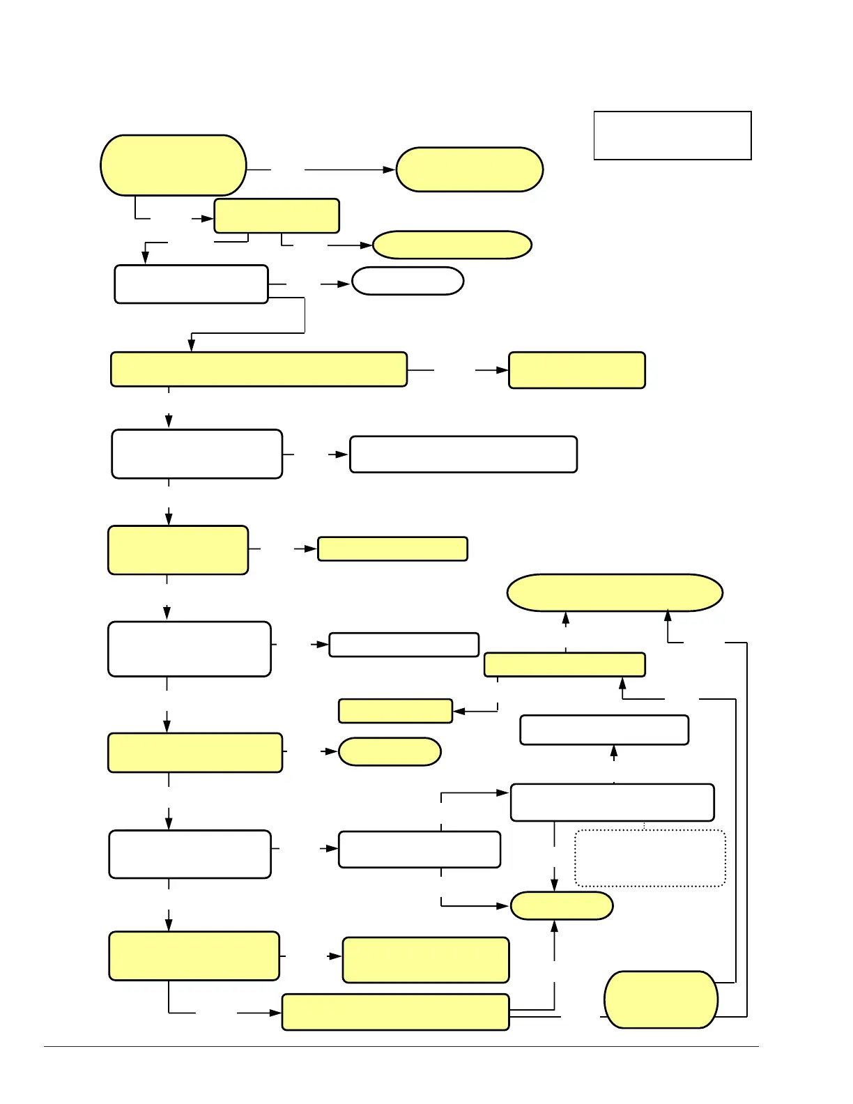
Cold Water Run Troubleshooting Guide
Ste
9
Ste
8
Ste
10
Step 1
Step 2
Step 3
Step 4
Step 5
Step 6
Step 7
Is there a Call For
Heat at the heate
?
Is the inverter in the
cold run controller powered?
Replace inverter or
correct wiring
Does the cold run inverter output 12VDC from PCS to the
reset switch
Pin S1 and
in FS of the cold run circuit board?
Replace circuit board
Are the terminals 1-2 of TB3
connected to N.O. contacts of
DPDT relay?
Does cold run terminal AL0
relay coil receive 24VAC
from MC on circuit board?
Are terminals 1-4 of TB3 correctly
connected back to the heater?
Call our Technical Service Department
1-805-278-5300
NO
Verify 120VAC* or 230VAC*
from separate circuit breaker
YES
Does TB1 of cold run
controller have 120VAC*
or 230VAC*?
Heater is in standby mode
Correct Wiring
YES
NO
NO
YES
YES
NO
NO
NO
YES
YES
NO
The unit is okay
YES
NO
YES
Correct wiring
Is the injector pump
modulating after 2-1/2
minutes?
NO
Correct wiring
YES
Is the heater tripping the high
limit?
YES
NO
Verify pump is rotating in proper
direction
Pump must decrease
RPM’s on decreasing 0-
10VDC signal
YES
Correct 3 phase pump wiring
NO
Is 24VAC present at CFH
connection on cold run circuit
board?
Check and verify 24VAC between pin 4 and 5
of TB3 in cold run controller and correct.
Is 0-10VDC present at
connection FR of cold run circuit
board and pin 0 of the inverter?
NO
Replace cold run circuit board
or correct wiring.
YES
Does cold run circuit board lock-out on
“Sensor out of Range”?
NO
YES
Is sensor resistance correct?
YES
NO
Replace sensor
Is the system
water temperature
º
NO
YES
*NOTE: See wiring diagrams
for proper supply voltage based
on inverter used on heater.
 Loading...