6
Before beginning the installation, it’s important to rst
inspect the system and determine what materials you will
need. Some parts are included with the controller while
others you will need to provide.
• 1 Control Box
• 1 Temperature Sensor
• 1 Cover
• 1 Valve assembly with actuator (Shipped separately).
• Wiring and mounting hardware (Provided by installer)
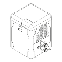
NOTE: After testing, the factory may ship the piping
assembly disassembled and attached to the heater
pallet. This is done to avoid shipping damage and it must
be reassembled on the jobsite. Use Figure 1 to assist in
reassembling the piping.
Figure 1. Cold Water Start Assembly
Installation
Check the Power Source
A
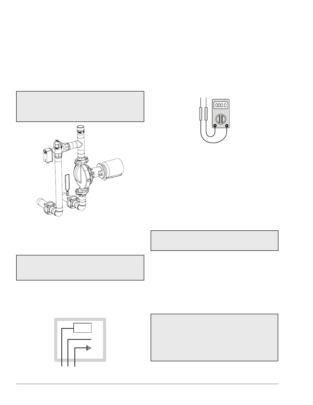
WARNING: Using a multi-meter, check the following
voltages at the breaker panel prior to connecting any
equipment. Make sure proper polarity is followed and
house ground is proven.
Check the power source:
• AC = 108VAC Minimum, 132VAC MAX
• AB = 108VAC Minimum, 132VAC MAX
• BC = <1VAC Maximum
CIRCUIT
BREAKER
WHITE
GROUND
BLACK
GREEN
Figure 2. Wiring Connections
Mounting the Control Box
The control box should be mounted on the side of the
heater to which the system piping and valve assembly are
to be attached as shown in Figure 4 through Figure 8. The
controller should be mounted so as to provide maximum
support by using the mounting holes provided on the base
of the controller to the side center brace on the heater. On
MVB and Hi Delta models, locating dimples are provided
for ease of drilling the mounting holes. You will need to
drill mounting holes through the heater side panel for the
routing of wiring and the sensor.
Figure 3. Multi-meter
Installing the Temperature Sensor
Avoid routing wiring on or near other electrical wires,
conduit, motors, spark igniters or other sources of high
intermittent voltage or current. The sensor should be
placed in the dry well on the inlet header, or as indicated
in the piping for multiple boilers, as shown on page 18.
Ensure it is installed using thermal paste (eld supplied)
and that it is held rmly at the bottom of the well.
Connecting the Valve Assembly
CAUTION: Miswiring the actuator may cause
unwarrantable damage. Verify the wire colors against
the actuator make and model.
Connect the valve assembly into the bypass piping. The
branch (port B) is connected to the crossover pipe (bypass
between inlet and outlet). The actuator tail stock should
be oriented to point down. Refer to the Actuator to Valve
Orientation section.
Route wiring from the valve to the controller through one
of the bottom panel conduit knockouts to TB2. Refer to
the wiring diagram provided on the inside of the controller
cover assembly.
A
CAUTION: Install the foil-faced insulation on the
inside of the rear panel of MVB heaters as indicated in
Figure 8. Use spray adhesive or high-temp foil tape to
attach the insulation. Ensure that the foil faces the heat
exchanger assembly. Failure to install this insulation
as directed can cause overheating of the components
and any resulting damage will not be covered under
warranty.
 Loading...