For non-communicating systems or
communicating systems with a non-
communicating condenser (see section
titled SPECIAL CONFIGURATION –
COMMUNICATING THERMOSTAT
AND FURNACE WITH A NON-COM-
MUNICATING CONDENSER of this
document), the target cooling airflow
will be determined by the adjustments
of SW1-1 and SW1-2. Furnaces with
½ HP motors will have a maximum tar-
get airflow setting of 1200 CFM.
Furnace with 1 HP motors will have a
maximum target airflow setting of 2000
CFM. The airflow achieved may be
less than the target if the static pres-
sure across the furnace is over 0.6” wc.
Consult the cooling equipment instruc-
tions and documents for target airflow
and adjust accordingly.
DIPSWITCHES
NNOOTTEE::
The integrated furnace control
does not recognize switch setting
changes while energized.
SW1
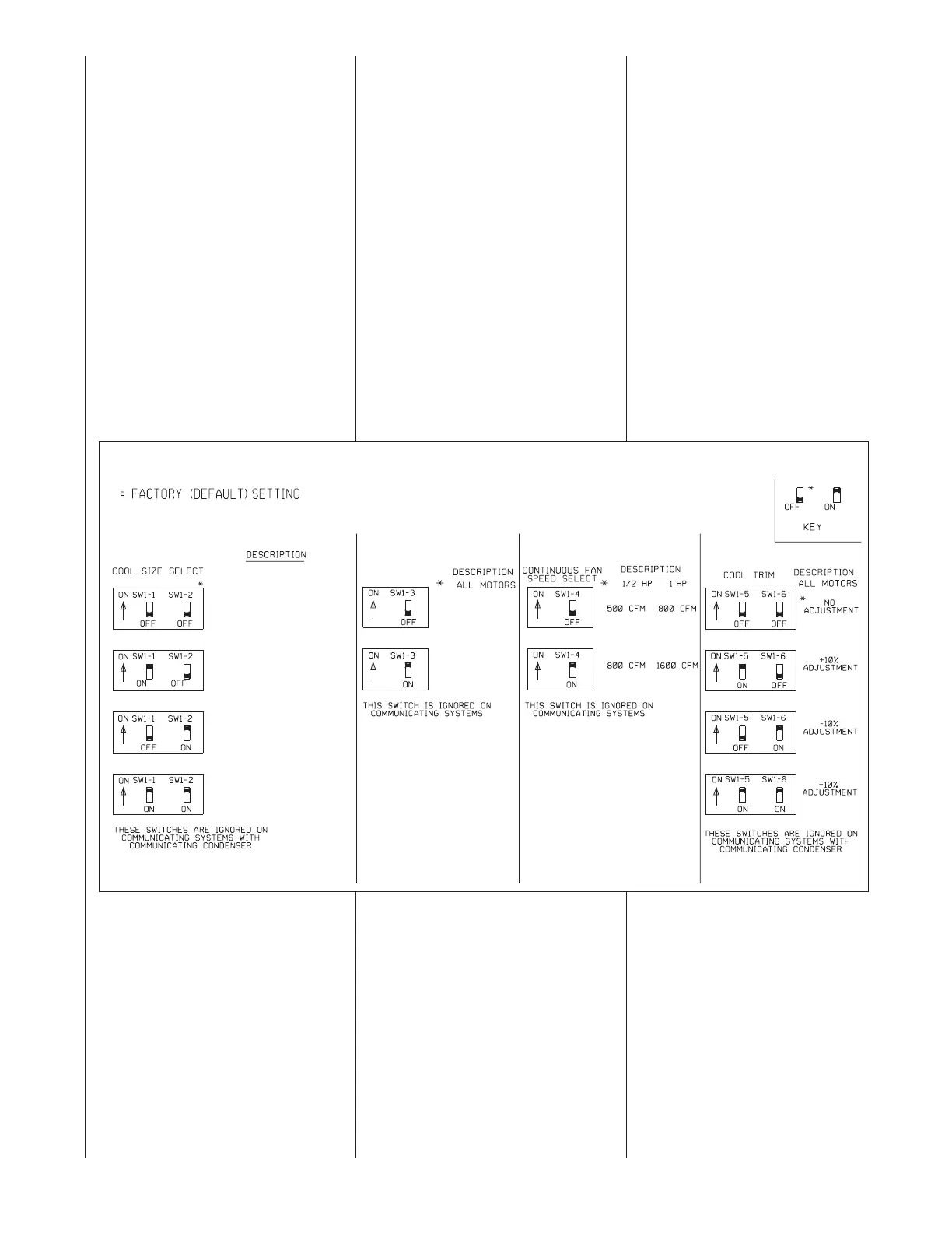
SW1-1 AND SW1-2 – COOLING AIR-
FLOW SELECT – These dipswitches
are used to select the appropriate cool-
ing airflow based on the amount
required. The switch settings do not
affect cooling airflow when installed with
a fully communicating condenser. In
that case, the condenser supplies the
information for cooling airflow which is
preset at the factory and not adjustable.
Cooling airflow for non-communicat-
ing systems can be adjusted
approximately +/- 10% by using the
cool trim adjustment dipswitches;
SW1-5 and SW1-6. See Figure 34.
Cooling airflow for non-communicat-
ing systems is also affected by the
settings of dipswitch position SW2-6.
This switch will determine the appro-
priate amount of airflow to be used
for the low stage (1
st
stage) of cool-
ing. See the tables in Figure 35.
More information can be found in
the section titled SW2 (SW2-6).
Consult the tables in Figures 34, 35
and 36 for target airflow settings and
adjustments based on the positions
of the dipswitches SW1-1, SW1-2,
SW1-5, SW1-6 and SW2-6.
FIGURE 34
DIPSWITCH BANK SW1
TIMED HEAT STAGING
NORMAL
NO STAGING
TIMED
STAGING
*
(-)GPE-05(-)BMKR (-)GPE-07(-)BRQR (-)GPE-10(-)BRMR
(-)GLE-05(-)BMKR (-)GLE-07(-)BRQR (-)GLE-10(-)BRMR
(-)GPE-07(-)AMKR (-)GPE-12(-)ARMR
(-)GLE-07(-)AMKR (-)GLE-12(-)ARMR
1200 CFM 1600 CFM 2000 CFM
1000 CFM 1400 CFM 1600 CFM
800 CFM 1200 CFM 1400 CFM
600 CFM 1000 CFM 1200 CFM
44
 Loading...