20
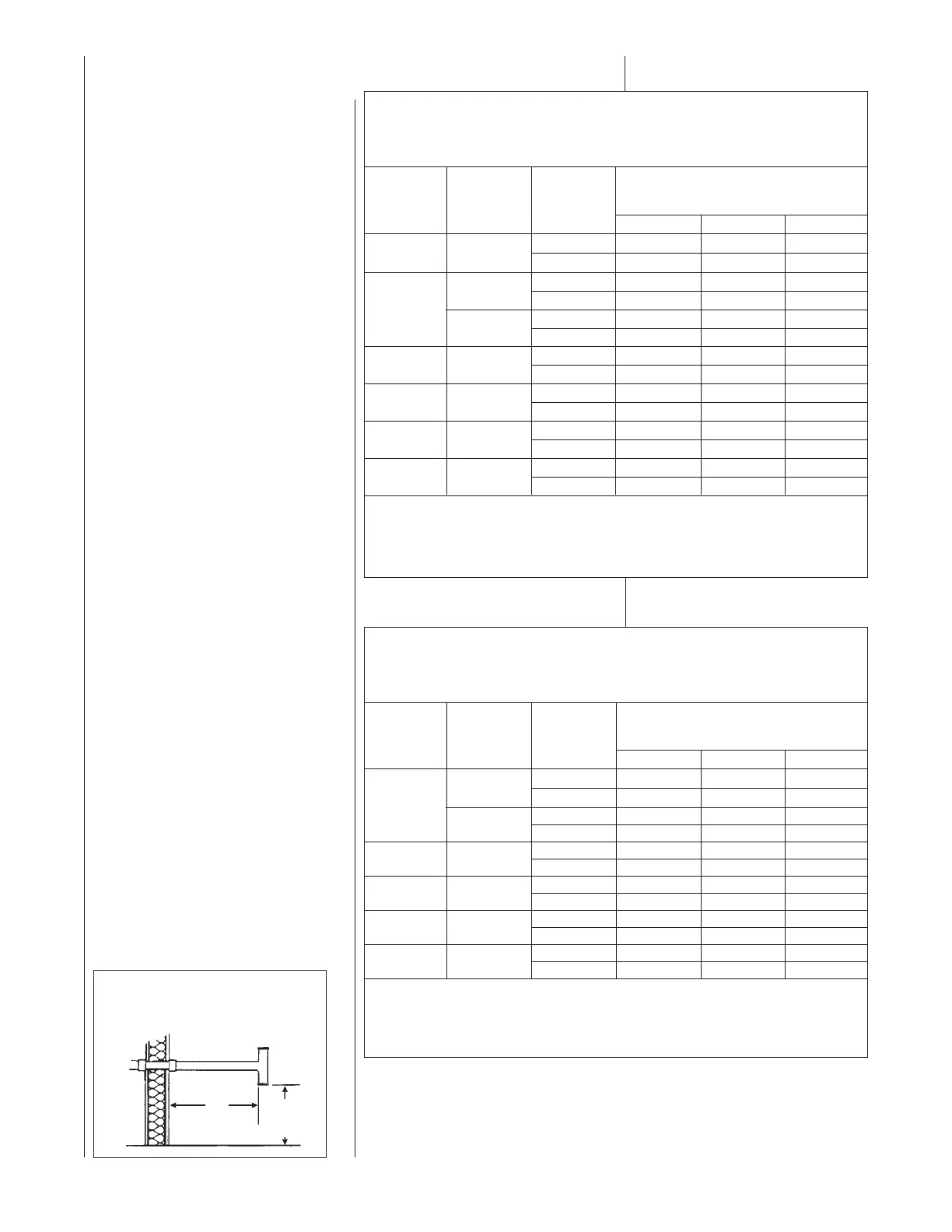
ELEVATED SINGLE PIPE ALTERNATE TEETERMINATION
See Figure 15. The tee termination may be elevated up to 24 inches above the
wall penetration if required for anticipated snow levels. Use 2 long-sweep, 2-in.
PVC elbows and 2-in. PVC pipe, attaching the tee so it is 12 inches from the wall.
NON-DIRECT VENT
INSTALLATION
GUIDELINES
IMPORTANT: Failure to correctly follow
all venting guidelines may result in
erratic furnace operation, freeze-up of
combustion air or exhaust air piping or
sooting of the furnace.
All exhaust piping must be installed in
compliance with Part 7, “Venting of
Equipment,” of the latest edition of the
National Fuel Gas Code NPFA54/ ANSI
Z223.1-, local codes or ordinances and
these instructions.
1. Vertical piping is preferred.
2. All horizontal piping must slope
upward a minimum of
1
/4 inch per
foot of run so that condensate drains
toward the furnace.
3. All horizontal runs must be
supported at least every 4 feet. No
sags or dips are permitted.
4. IMPORTANT: Do not common vent
with any other appliance. Do not
install in the same chase or chimney
with a metal or high temperature
plastic pipe from another gas or fuel-
burning appliance unless the
required minimum clearances to
combustibles are maintained
between the pvc pipe and other
pipes.
5. All vent runs through unconditioned
spaces where below-freezing
temperatures are expected should
be insulated with 1-in. thick,
medium-density, foil-faced
fiberglass. An equivalent “arm-a-
flex” or “rub-a-tex” insulation may
also be used as long as there is no
heat tape applied to the vent pipe.
For horizontal runs where water may
collect, wrap the vent pipe with self-
regulating 3 or 5 watt heat tape. The
heat tape must be U.L. listed and
installed per the manufacturer’s
instructions.
6. The minimum vent pipe length is
5 feet.
7. Extend the exhaust pipe a minimum
of 18” from the cabinet before turning
vent.
8. Vent cannot be ran underground.
FIGURE 14
TEE TERMINAL – FOR STANDARD
HORIZONTAL NON-DIRECT
INSTALLATION
VENT
12"
12" MIN. ABOVE
GRADE OR
SNOW LEVEL
NUMBERS OF ELBOWS
45° OR 90°
Medium / Long Radius ONLY
1-2 3-4 5-6
2”
Standard 60 55 50
45,000
Alternate 55 50 45
2”
Standard 30 25 20
Alternate 25 20 15
60,000
3”
Standard 120 120 115
Alternate 120 120 110
3”
Standard 45 40 NA
75,000
Alternate 45 45 NA
3”
Standard 90 85 75
90,000
Alternate 60 50 45
105,000 3”
Standard 45 40 NA
Alternate 45 45 NA
120,000 3”
Standard 70 65 55
Alternate 40 30 25
NOTES:
1. *N.A. - NOT APPLICABLE.
2. MAXIMUM OF 6 ELBOWS MAY BE USED. DO NOT COUNT ELBOWS REQUIRED FOR
ALTERNATE TERMINATION. USE ONLY MEDIUM OR LONG SWEEP ELBOWS.
3. A 45 OR 22.5 DEGREE ELBOW IS CONSIDERED ONE ELBOW.
4. NO SCREENS MAY BE USED TO COVER EXHAUST.
*A = 17-1/2” CABINET WIDTH B = 21) CABINET WIDTH
FURNACE
INPUT
VENT PIPE INSTALLATION
PIPE
SIZE
TERMINATION
TABLE 2
UPFLOW UNITS
FOR NON-DIRECT VENT APPLICATIONS - AIR FOR COMBUSTION
PROVIDED FROM INDOORS
MAXIMUM ALLOWABLE LENGTH IN FEET OF EACH EXHAUST PIPE AND INTAKE PIPE
NUMBERS OF ELBOWS
45° OR 90°
Medium / Long Radius ONLY
1-2 3-4 5-6
2”
Standard 40 35 30
Alternate 30 25 20
60,000
3”
Standard 120 120 120
Alternate 110 105 100
3”
Standard 120 120 120
75,000
Alternate 100 95 85
90,000 3”
Standard 110 105 95
Alternate 50 40 35
105,000 3”
Standard 65 60 55
Alternate 50 40 35
120,000 3”
Standard 40 35 30
Alternate 40 35 30
NOTES:
1. *N.R. - NOT RECOMMENDED.
2. MAXIMUM OF 6 - 90 DEGREE ELBOWS MAY BE USED. DO NOT COUNT ELBOWS REQUIRED FOR
ALTERNATE TERMINATION. USE ONLY MEDIUM OR LONG SWEEP ELBOWS.
3. A 45 OR 22.5 DEGREE ELBOW IS CONSIDERED ONE ELBOW.
4. NO SCREENS MAY BE USED TO COVER EXHAUST.
*A = 17-1/2” CABINET WIDTH B = 21” CABINET WIDTH
FURNACE
INPUT
PIPE
SIZE
TERMINATION
TABLE 3
DOWNFLOW/HORIZONTAL UNITS
FOR NON-DIRECT VENT APPLICATIONS - AIR FOR COMBUSTION
PROVIDED FROM INDOORS
MAXIMUM ALLOWABLE LENGTH IN FEET OF EACH EXHAUST PIPE AND INTAKE PIPE
 Loading...