NOTE: A load calculation must be
performed to properly determine the
required furnace BTU size for the
structure. Also, the duct must be properly
designed and installed for proper airflow.
Existing ductwork must be inspected for
proper size and sealed system. Proper
airflow is necessary for both user comfort
and equipment performance.
Before opening the furnace carton and
installation of the furnace, verify the data
tags on the carton and inside the
furnace, match and is what was ordered
from the local distributor. Also, check for
any damage to the furnace before
installation.
IMPORTANT: Proper application,
installation and maintenance of this
furnace and system is a must if
consumers are to receive the full benefits
for which they have paid.
The (-)GRK-, (-)GRL-, (-)GTK- series
furnaces are design-certified by CSA for
use with natural and propane gases as
follows:
4
1. As non-direct vent central forced air
furnaces taking combustion air from
the installation area or using air
ducted from the outside.
2. As direct vent central forced air
furnaces with all combustion air
supplied directly to the furnace
burners through a special air intake
system outlined in these
instructions.Install this furnace in
accordance with the American
National Standard Z223.1 – latest
edition entitled “National Fuel Gas
Code” (NFPA54) and requirements
or codes of the local utilities or
other authorities having jurisdiction.
This is available from the following:
National Fire Protection
Association, Inc.
Batterymarch Park
Quincy, MA 02269
CSA-INTERNATIONAL
8501 East Pleasant Valley Road
Cleveland, Ohio 44131-5575
GENERAL INFORMATION
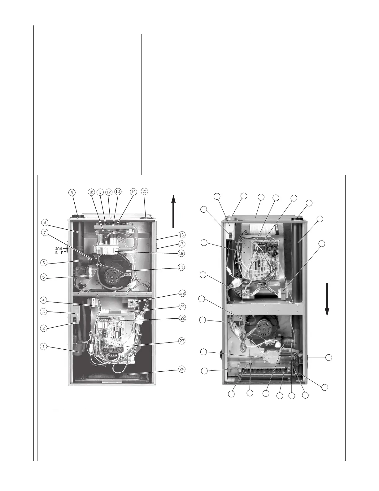
FIGURE 1
UPFLOW FURNACE COMPONENTS
ITEM
NO. PART NAME
1 CONDENSATE TRAP
2 DOOR SWITCH
3 JUNCTION BOX
4 TRANSFORMER
5 PRESSURE SWITCHES
6 EXHAUST TRANSITION
7 CONNECTOR
8 OUTLET AIR PIPE
9 SHIPPING PLUG (TO BE REMOVED)
10 FLAME SENSOR
11 OVERTEMPERATURE SWITCH
12 TOP PLATE
13 BURNER
14 IGNITER
15 COMBUSTION AIR INLET
16 OPTIONAL AIR INLET (UPFLOW UNITS ONLY)
17 OPTIONAL GAS INLET
18 GAS VALVE
19 INDUCED DRAFT BLOWER
20 CAPACITORS
21 BLOWER
22 LOW VOLTAGE TERMINAL
23 CONTROL MOUNTING PLATE
24 FILTER / SOLID METAL BASEPLATE (UPFLOW
UNITS ONLY)
25 BURNER COVER PLATE
(DOWNFLOW/HORIZONTAL UNITS ONLY)
NOTE: A PARTS BAG IS INCLUDED WITH THE FURNACE. IF A NEW
PARTS BAG NEEDS TO BE ORDERED, USE THE FOLLOWING PART
NUMBERS: AS-100717-01 FOR (-)GRL-45, (-)GRL-60, (-)GRK-75, (-)GRL-
90 AND (-)GRK-105 AS-100717-02 FOR (-)GRK-120
DOWNFLOW/HORIZONTAL FURNACE COMPONENTS
NOTE: A PARTS BAG IS INCLUDED WITH THE FURNACE. IF A NEW
PARTS BAG NEEDS TO BE ORDERED, USE THE FOLLOWING PART
NUMBERS: AS-100717-03 FOR (-)GTK-60, (-)GTK-75, (-)GTK-90, (-)GTK-
105 AND (-)GTK-120
AIRFLOW
9
8
4
17
11
25
10
18
5
19
20
21
2
3
15
12
23
22
7
1
14
6
13
AIRFLOW
Install units in Canada in accordance
with CSA-B149, local installation
codes and authorities having
jurisdiction. CSA-B149 is available
from:
CSA-INTERNATIONAL
178 Rexdale Blvd.
Toronto, Ontario
Canada M9W, 1R3
NOTE: It is our recommendation that
any HVAC equipment which were
subject to flooding be replaced to
avoid any risk of property damage,
personal injury or death. Also, our
position that the immersion by flood
waters compromises any HVAC
products thus voiding this warranty.
NOTE: Models having option code 320
added at the end of the model number
designation are shipped factory ready
for a horizontal only installation. The
drain trap for downflow installation is
not included in the parts bag for these
appliances.
 Loading...