23
INSTALLATION
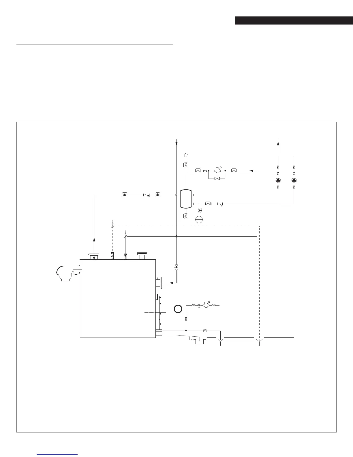
2.7 Typical water system schematics
The following P&ID represent the typical arrangement for the most
common types of installation and they are only a suggestion for
the installer that is resposible for all equipment and details re-
quired by local laws.
9
The DHW and central heating circuits must incorporate ex-
pansion vessels of adequate capacity as well as suitably rated
safety valves. The condensate drain must be connected to a
suitable collection and drain system.
9
The choice of system components and the method of their
installation are left up to the heating engineer installing the
system. Installers must use their expertise to ensure proper
installation and functioning in conformity to all applicable
legislation.
9
If needed, water supplies and recovery circuits must be condi-
tioned by suitable treatment systems. Refer to the values list-
ed in the table in the paragraph Water quality requirements.
0
It is prohibited to operate the circulators without water.
Single Boiler Piping Schematic
1
3
15
6
3
3
3
11
3
3
3
3
MAKE-UP
WATER
16
16 1617
FLOW
7*
15
10
1
10
12
3
3
3
9
WATER INLET
7
5
3
5
4
3
3
4
3
8
2
18
M
CENTRAL
HEATING
RETURN
LT
RETURN
HEATING
SUPPLY
1 Boiler
2 Burner
3 Isolation valves
4 Central heating system pump
5 Non-return valves
6 Automatic vent valve
7 Boiler safety valve
7* Second boiler safety valve (only for RTC 8000 - RTC
10000)
8 Boiler drain valve
9 Y lter
10 Pressure reducer
11 Expansion tank
12 Water softener lter
13 Siphon
14 Condensate outlet
15 Drain
16 Isolation valve
17 Non-return valve
18 Air separator
M Pressure gauge
(*)_HT High Temperature
LT Low Temperature
_ _ _ RTC 8000 - RTC 10000
 Loading...