2. Connect the ground alligator clip or spring of the probe to the circuit
ground terminal, and then connect the probe tip to the circuit point to be
tested.
Figure 6 To Connect the Passive Probe
After you connect the passive probe, check the probe function and probe
compensation adjustment before making measurements. For detailed
procedures, refer to "Function Inspection" in this manual and the "Probe
Compensation" section introduced in
MSO5000 User's Guide
.
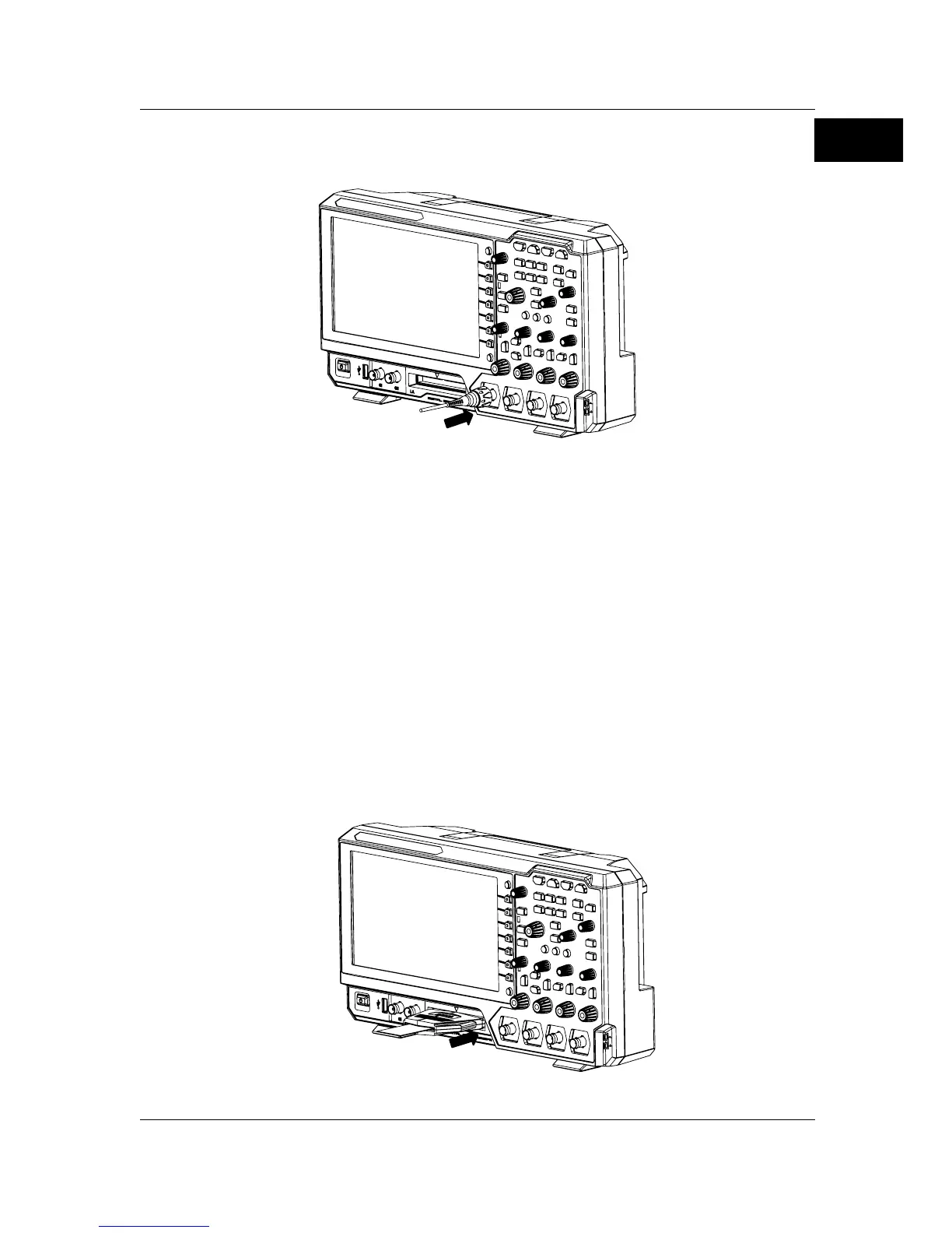
Connect the logic probe:
1. Connect the output terminal of the logic probe to the digital channel input
terminal on the front panel of the oscilloscope in the correct direction, as
shown in Figure 7.
2. Connect the other terminal of the logic probe to the signal terminal under
test. RIGOL's MSO5000 series supplies PLA2216 active logic probe option.
To apply to different application scenarios, PLA2216 provides two
connection methods to connect the signal under test. For details, refer to
PLA2216 Active Logic Probe User’s Guide
.
Figure 7 To Connect the Logic Probe

 Loading...