Publication 1769-UM002B-EN-P - July 2005
Installation and Wiring 2-7
Panel Mounting
Mount the module to a panel using two screws per module. Use M4 or #8
panhead screws. Mounting screws are required on every module.
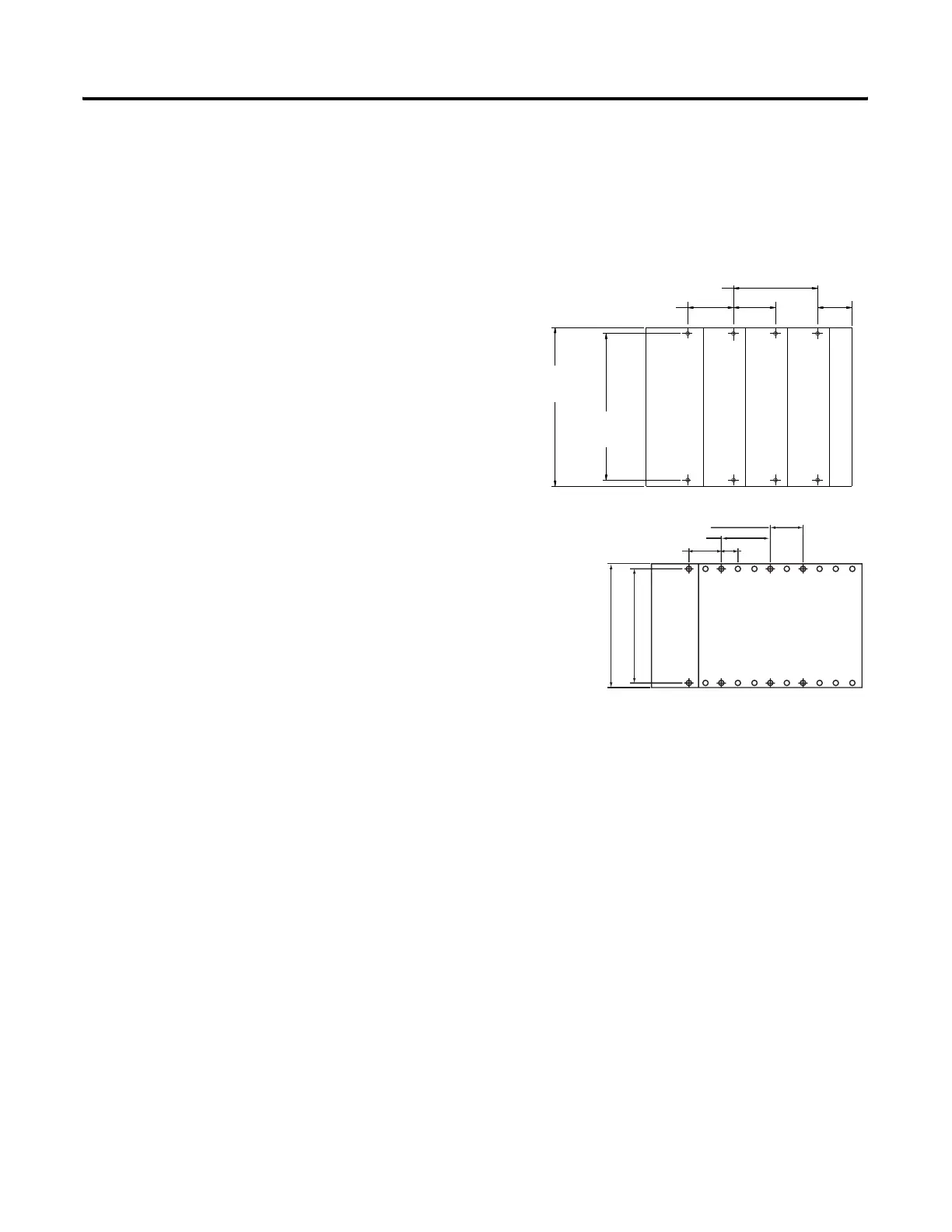
Figure 2.3 Panel Mounting Using the Dimensional Template
Figure 2.4 Panel Mounting for the 1769-IF8 Using the Dimensional Template
132
(5.197)
122.6±0.2
(4.826±0.008)
35
(1.38)
28.5
(1.12)
Compact I/O
Compact I/O
Compact I/O
Host Controller
Refer to host controller documentation for this dimension.
For more than 2 modules: (number of modules-1) X 35 mm (1,38 in.).
Right End Cap
NOTE: All dimensions are in mm (inches).
Hole spacing tolerance: ±0.04 mm (0.016 in.).
l Mounting
Host Controller
Refer to host controller documentation for this dimension.
Spacing for single-wide modules 35 mm (1.378 in).
NOTE: Overall hole spacing
tolerance: ±0.4 mm (0.016 in.)
Spacing for one-and-a-half-wide modules 52.5 mm (2.067 in).
Locate holes every 17.5 mm (0.689 in) to allow for a
mix of single-wide and one-and-a-half-wide modules
(e.g., 1769-OA16).

 Loading...


