6 Rockwell Automation Publication 1783-IN011B-EN-P - April 2023
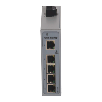
Stratix 2500 Lightly Managed Switches Installation Instructions
Site Requirements
When determining where to place the switch, observe these guidelines:
• Cabling is away from sources of electrical noise, such as radios, power lines, and fluorescent lighting fixtures.
• For 10/100 ports, the cable length from a switch to an attached device cannot exceed 100 meters (328 ft).
Mount the Switch
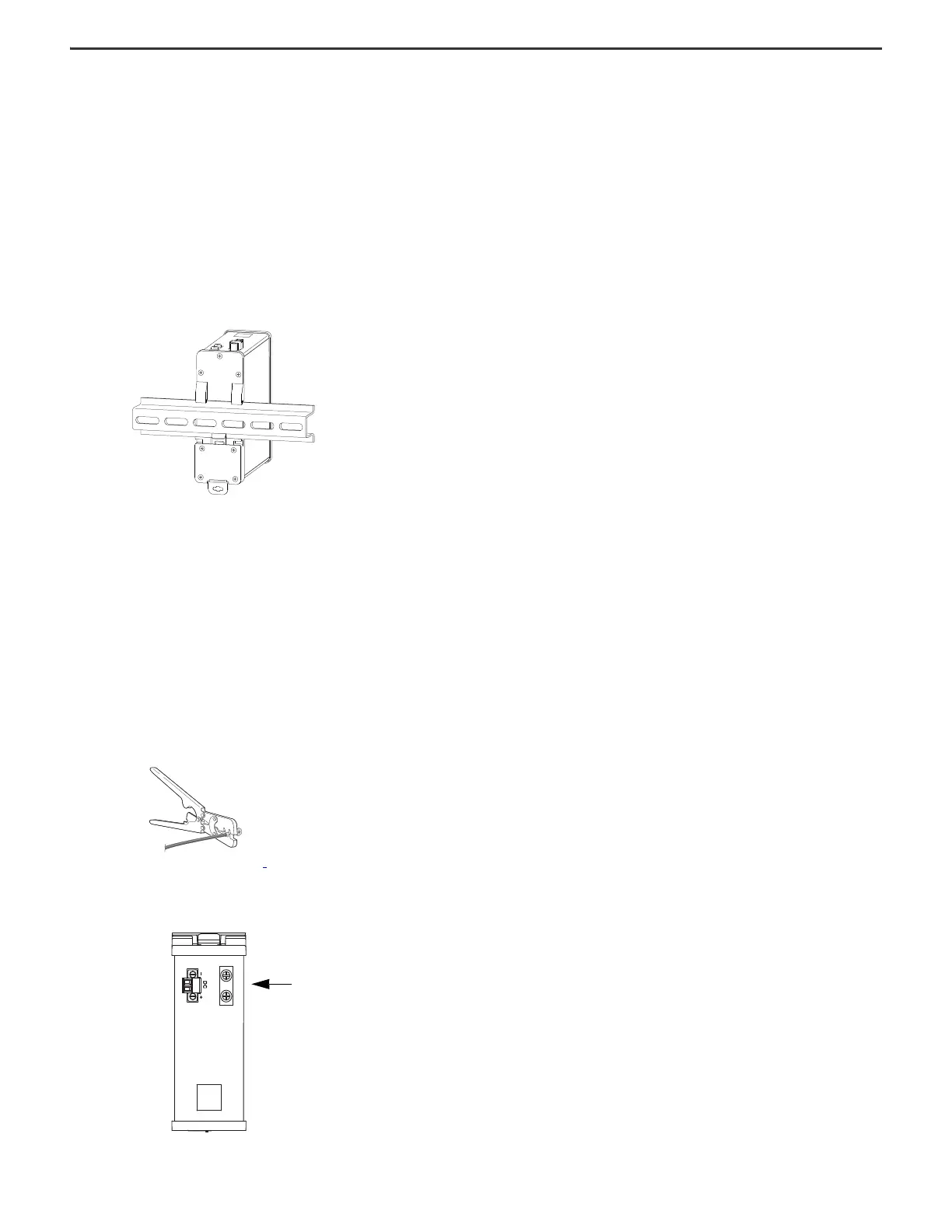
The switch ships with a spring-loaded latch on the rear panel that you can use to mount the switch on a DIN rail.
To mount the switch to a DIN rail, follow these steps.
1. Position the rear panel of the switch directly in front of the DIN rail, making sure that the DIN rail fits in the space between the two hooks near the top of the switch and the
spring-loaded latch near the bottom.
2. Holding the bottom of the switch away from the DIN rail, place the two hooks on the back of the switch over the top of the DIN rail.
3. Push the switch toward the DIN rail to cause the spring-loaded latch at the bottom rear of the switch to move down, and snap into place.
Ground the Switch
The ground lug is not supplied with the switch. You can use one of these options:
• Single ring terminal
• Two single ring terminals
To ground the switch to earth ground by using the ground screw, follow these steps:
1. Use a standard Phillips screwdriver or a ratcheting torque screwdriver with a Phillips head to remove the ground screw from the top panel of the switch.
Store the ground screw for later use.
2. Use the manufacturer’s guidelines to determine the wire length to be stripped.
3. Insert the ground wire into the ring terminal lug, and use a crimping tool to crimp the terminal to the wire.
If you are using two ring terminals, repeat this action for the second ring terminal.
4. Slide the ground screw from step 1
through the ring terminal.
5. Insert the ground screw into the functional ground screw opening on the top panel.
6. Use a ratcheting torque screwdriver to tighten the ground screws and ring terminal lugs to the switch top panel.
The torque must not exceed 0.51 N•m (4.5 in•lb).
7. Attach the other end of the ground wire to a grounded bare metal surface, such as a ground bus, a grounded DIN rail, or a grounded bare rack.
 Loading...