TLSZR/L-GD2
8 10000302608 Ver 00 July 2012
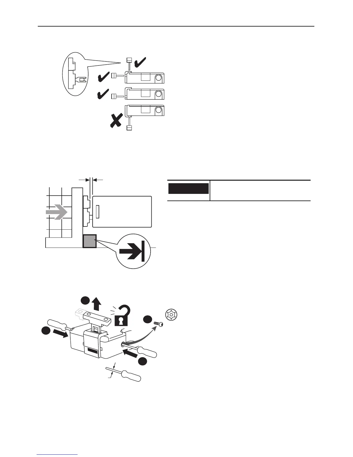
Allowable Approach Directions
Clearance in Closed Position [mm (in)]
(and Maximum Actuator Insertion Distance for Locking)
Auxiliary/Manual Release [mm (in.)]
The actuator and target should always be
mounted as “close coupled” and can
approach the switch in any of the three
entry slot positions shown.
Approach from the underside is not
allowed.
Minimum clearance: 2 (0.08)
Maximum assured locking distance: 5 (0.20)
Do not use the switch as a guard
stop.
T20
≤ 2.5 (0.098) dia.
1
3
2
2
If power is supplied to the switch and the
switch is in the locked state, operation of
the auxiliary release will cause the switch to
enter a fault condition (blinking red LED).
To reset the switch, cycle the power.
 Loading...