Trusted Power System 2. Assembly
Rockwell Automation Publication PD-T823X Issue 11 5
2. Assembly
A pair of brackets mounted in to a 19 inch frame supports up to 4 Power Shelves and are
required to provide support at the rear of the Power Shelf.
The brackets supplied mount the equipment by its 19 inch rack ears and provide a box
structure to brace the power supplies. The back of the power supplies are fixed using M3.5
screws that are fixed via tapped holes in the Power Shelf. The front of the Power Shelf is
located and supported via screws through the lugs of the Power Shelf.
The mounting bracket occupies 4U and can accommodate up to 4 Power Shelves. The
design is such that no space outside the 4U aperture is required. When installed it is
possible to remove individual Power Shelves should this be required. The design of the
mounting bracket does not obstruct access to the front or back of the Power Tray.
Power Packs are slotted into the 1U Power Shelf with the first Power Pack in the right hand
slot, as shown in Figure 4. Each Power Pack provides 750 W (31.25 A at 24 Vdc) to the DC
output on the Power Shelf.
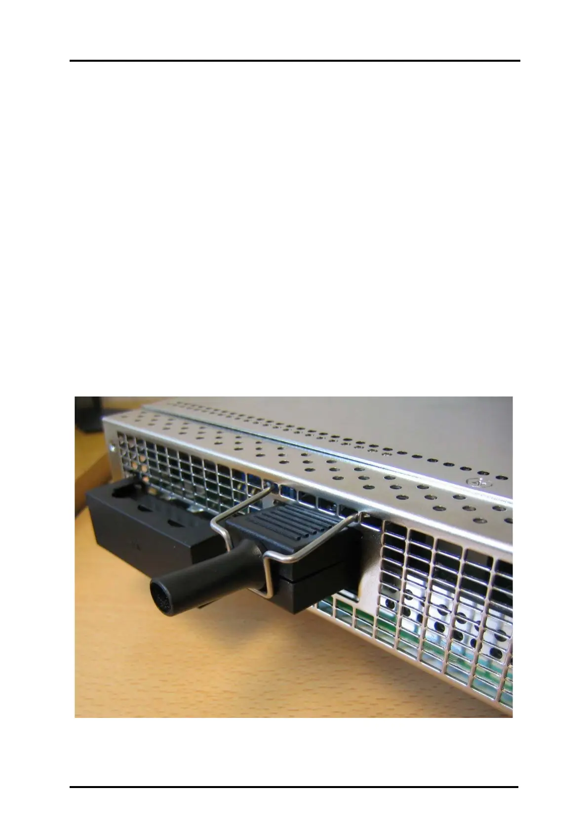
The standard AC input connection to the Power Shelf is through IEC 60320 type connectors
rated at 10 A/250 Vac in Europe/Asia and 15A/120 Vac in North America.
Figure 3 AC Power Connectors and Retaining Clips
 Loading...