Effectivity: 914 Series BRP-Powertrain page 7-8
OM Edition 2 / Rev. 0 April 01/2009
d04479.fm
7.4) Electric system
General note See Fig. 4
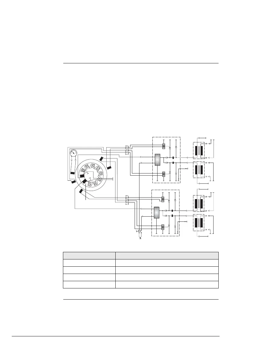
The ROTAX 914 engine is equipped with a dual ignition unit of a
breakerless, capacitor discharge design, with an integrated gene-
rator.
The ignition unit needs no external power supply.
Charging coils Two independent charging coils (1) located on the generator sta-
tor supply one ignition circuit each. The energy is stored in capa-
citors of the electronic modules (2). At the moment of ignition 2
each of the 4 external trigger coils (3) actuate the discharge of the
capacitors via the primary circuit of the dual ignition coils (4).
NOTE: The trigger coil (5) is provided for the rev coun-
ter signal.
Firing order: 1-4-2-3.
Fig. 4
00425
Part Function
1 charging coils
2 electronic modules
3,5 trigger coils
4 dual ignition coils
4
4
4
4
2
2
3
1
3
5
Ignition circuit A
Ignition circuit B