9) Once the flue gas value has stabilised -
at the earliest 3 minutes after burner start
- adjust the O
2 content ± 0.1 % or the CO
2
content ± 0.2 % to the selected value in
Tab. 5.1.2 or Fig. 5.1.7/5.1.8 using the
mixture adjusting screw (pos. 11):
- turning anti-clockwise: more gas O
2 CO2
- turning clockwise: less gas O
2 CO2
10) Start the emissions test function to ramp
up to the minimum load (see chapter 8).
11) Once the flue gas value has stabilised -
at the earliest 2 minutes after changing
the output - compare the actual values
with those in Table 5.1.2 or Fig. 5.1.7/
5.1.8. In case of excessive deviations or if
the burner whistles, adjust the O2 content
± 0.1 % or the CO2 content ± 0.2 % to the
minimum set value using the gas pressure
adjusting screw (pos. 12):
- turning anti-clockwise: lower gas output
pressure O2 CO2
- turning clockwise:
higher gas output O2 CO2
12) Switch the emission test function
ON to ramp up to maximum load
13) Check the combustion values. The
adjustment is completed if the actual
values meet the defaults in step 9.
Otherwise repeat steps 9 to 13.
Important: The gas valves are
preset at the factory. Generally
the gas pressure governor
requires no further adjustment. The
adjusting screw is hidden under a cover.
If the adjusted value deviates excessively
from the set value and the burner tends to
whistle, alter the adjustment only in small
steps (maximum 1/2 turn per adjustment).
After each adjustment, wait a while (at
least two minutes) until the flue gas
analyser has settled down again.
Set the minimum output to a higher level if
the burner becomes noisy at the lowest
output (subject to weather conditions).
Any output adjustments at the system (only
heating contractor), record these on the adjust-
ment label below the type plate (burner load in
accordance with Fig. 8.4). For the burner
adjustment values subject to load, see Fig.
5.1.7 or Fig. 5.1.8.
[ 39 ]
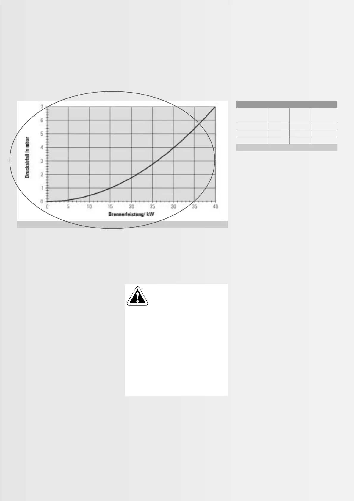
Fig. 5.1.9: Pressure drop in the gas supply hose
Gas type Inlet pressure in mbar
1)
Rated min max.
pressure
Natural gas E, H 20 17.0 25.0
Natural gas LL, L 20 17.0 25.0
LPG
2)
50 42.5 57.5
Table 5.1.3: Gas supply pressure
1)
Notify your gas supply company if the gas
supply pressure falls outside the stated range.
2)
Where the rated pressures deviate, observe
the limits in accordance with the regulations
of the relevant country.