3
FEATURES
FENCE ASSEMBLY
Provides an adjustable surface to support and guide
work. The fence may be adjusted to compensate for the
stock reduced in the cut.
UNDERTABLE GUARD
Ensures that your hands, loose clothing and other objects
do not come in contact with the cutter or collet during
operation.
WARNING
The under table guards must be securely in
place before using the router table. Failure to do
so could result in serious personal injury.
CAUTION:
Keep the cord away from the router table surface
and position the cord so that it will not be caught
on lumber, tools or other objects during routing.
SAFETY GUARD
Provides a barrier to protect the operator from careless
contact with the cutter. The safety guard is adjustable for
all types of cuts and materials.
■ The safety guard will slide-up when the work piece is
pushed into the guard.
LIVE TOOL INDICATOR
This tool features a live tool indicator (9) which
illuminates as soon as the tool is connected to the supply.
This warns the user that the tool is connected and will
operate when the switch is pressed.
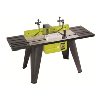
DESCRIPTION
1. Fence assembly
2. Die cast aluminium table
3. Table leg
4. Switch box assembly
5. Under table guard
6. Mitre gauge
7. Safety guard
8. Throat plates
9. Live Tool indicator
10. Switch
11. Pressure clamp
12. Feather board
13. Step riser
14. Sleeve
SPECIFICATION
Table Dimensions 610 x 355mm
Extension Table 355 x 200mm
Safety Guard / Dust Hook-up ø 57mm
Maximum Cutter Depth 37.9mm
Table Height 450mm
Mitre Slot 6.5 x 16 x 610mm
Weight 16kg
ASSEMBLY
LEG ASSEMBLY (Fig. 1)
■ Place router table upside down on a flat, level surface,
so that the front edge is closest to you. Position legs
as shown.
■ Align the four holes in each leg with the four
corresponding threaded holes in each corner of the
table.
SWITCH BOX ASSEMBLY (Fig. 2)
■ Hold the switch box so that the words ON (“I”) and
OFF (“O”) are aligned vertically (On ‘on top’ Off
‘below’).
■ Carefully screw the switch box underneath the router
table with the screws provided.
UNDER TABLE GUARD ASSEMBLY (Fig. 3)
■ Locate the under table guard. Position around the
throat of the table so that the three holes of the guard
line up with the three threaded holes in the table and
securely attach using bolts provided.
FENCE ASSEMBLY (Fig. 4)
■ Turn the fence assembly over and locate the four
small circular tabs. Position the fence on the router
table so that the tab engage on each channel of the
table.
■ Locate the two nuts and fence lock knobs.
Position a square nut inside the channel located
underneath the table. Insert the lock knob through the
hole in the fence assembly and screw it into the
square nut below. Repeat for the other side.
ART3-manual(RTA).qxd 9/10/04 4:23 PM Page 3
 Loading...