OPERATION
WARNING
Direction of feed for work piece is always against
the sharp edges of the bit, therefore into the
rotation of the cutter. Failure to heed this warning
is likely to result in serious personal injury.
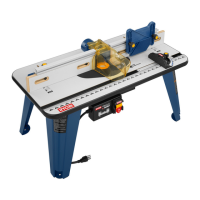
PREPARING FOR OPERATION (Fig. 13)
■ Unplug the router table.
■ Always plug the router into table switched outlet.
Never plug a router table mounted router into another
power source.
■ Direction of feed of the work piece is from right to left
or from the back of the router toward the front with the
bit located in the fence opening.
WARNING
Failure to unplug your router could result in
accidental starting causing possible serious
injury.
■ Direction of feed must always be so that the work
piece is being thrust against the sharp edges of the
rotating bit.
■ The work piece must always be tight against the
guide fence, unless a ball-bearing piloted bit is being
used. The infeed fence should be adjusted to support
the uncut work piece while the outfeed fence should
be adjusted properly to support the work piece after
the cut passes the router bit, compensating for the
removed stock.
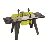
FITMENT OF THE TABLE EXTENSION (Fig. 13)
■ Using the nuts and washers provided in the bag fit the
extension bar to the table using the 2 holes at the
table ends. Ensure the male threaded end is used.
■ Fit both extension bars. Using the flats at the end of
each extension bar (nearest the Router table) tighten
using the spanners provided.
■ Slide the extension table over the extension bars
ensuring the name is facing you and located towards
the rear of the table.
■ Using the screws provided in the bag screw the table
to the extension bars and tighten.
■ To remove, reverse the mounting instructions.
FITMENT OF THE TABLE DUST EXTRACTION
SYSTEM
■ Place the black part of the dust extraction module in
the centre of the guide piece and align the 4 screw
holes on the dust extraction module to the 4 screw
holes on the guide piece.
■ Using the 4 screws provided in the bag screw the
dust extraction module in place securely.
■ If using a 31mm diameter extraction hose, insert the
sleeve (14) (Fig 11) into the rear of the dust extraction
module.
■ If using a 57mm diameter hose, remove the insert
from the rear of the dust extraction module.
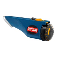
ROUTER SWITCH LOCK ON CLAMP
PREPARING FOR OPERATION (Fig. 14)
■ Lock the router switch by clamp which is provided
together with router table packaging.
■ Press the router on/off switch in to the on position.
■ Place the lock on clamp over the on/off switch.
■ Fasten the screw until the on/off switch is locked on
by the clamp.
■ Always control the power to the router with router
table switch whenever the router is mounted on the
table.
■ The lock on clamp is only necessary on models
ERT1250VN and ERT1500VK.
WARNING
Failure to unplug your router could result in
accidental starting causing possible serious
injury.
MAINTENANCE
WARNING
Do not at any time let brake fluids, petrol,
petroleum based products, penetrating oils etc.
come in contact with plastic parts. They contain
chemicals that can damage, weaken or destroy
plastic.
CAUTION:
When servicing, use only identical replacement
parts. Use of any other parts may create a
hazard or cause product damage.
6
ART3-manual(RTA).qxd 9/10/04 4:23 PM Page 6
 Loading...