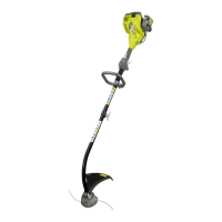
DESCRIPTION
Please refer to gure sheet.
1. Primer bulb
2. Choke lever
3. Fuel cap
4. Starter grip
5. On/off switch
6. Throttle trigger
7. Rear handle
8. Front handle
9. Upper shaft
10. Safety guard
11. Bump head
12. Cutting line
13. Knob
14. Throttle lock
15. Idle speed screw
16. Bolt
17. Wing nut
18. Flat washer
19. Wrench
20. Paper tube
21. Hex nut
22. Button
23. Guide recess
24. Coupler
25. Trimmer attachment shaft
26. Spark plug
27. Spark plug boot
28. Metal spark plug boot
ASSEMBLY
UNPACKING
This product requires assembly.
■ Carefully remove the tool and any accessories from
the box. Make sure that all items listed in the packing
list are included.
■ Inspect the tool carefully to make sure no breakage or
damage occurred during shipping.
■ Do not discard the packing material until you have
carefully inspected and satisfactorily operated the tool.
WARNING
If any parts are damaged or missing, do not operate
this tool until the parts are replaced. Failure to heed this
warning could result in serious personal injury.
WARNING
Do not attempt to modify this product or create
accessories not recommended for use with this
product. Any such alteration or modication is misuse
and could result in a hazardous condition leading to
possible serious personal injury.
WARNING
To prevent accidental starting that could cause serious
personal injury, always disconnect the engine spark
plug wire from the spark plug when assembling parts.
WARNING
Never attach or adjust any attachment while power
head is running. Failure to stop the engine may cause
serious personal injury.
WARNING
Be certain the knob is fully tightened before operating
equipment; check it periodically for tightness during use
to avoid serious injury.
PACKING LIST
■ Trimmer
■ Trimmer attachment shaft
■ Front handle assembly
■ Safety guard assembly
■ Bump head assembly
■ Wrench (2 types)
■ Operator's Manual
■ Figure sheet
■ Engine oil
ATTACHING THE FRONT HANDLE
See gure 2a.
■ Remove the bolt, flat washer, and wing nut from the
front handle.
■ Install the front handle onto the upper shaft at the
position between foam and warning label.
■ Replace the bolt, flat washer, and wing nut.
■ Tighten the wing nut.

 Loading...