4.4.4. Connecting the Grid and Backup Loads
Prerequisite
Select cables according to the below specification. You can amplify appropriate diameter selection of the
alternating current (AC) cable for the long grid-connection distance.
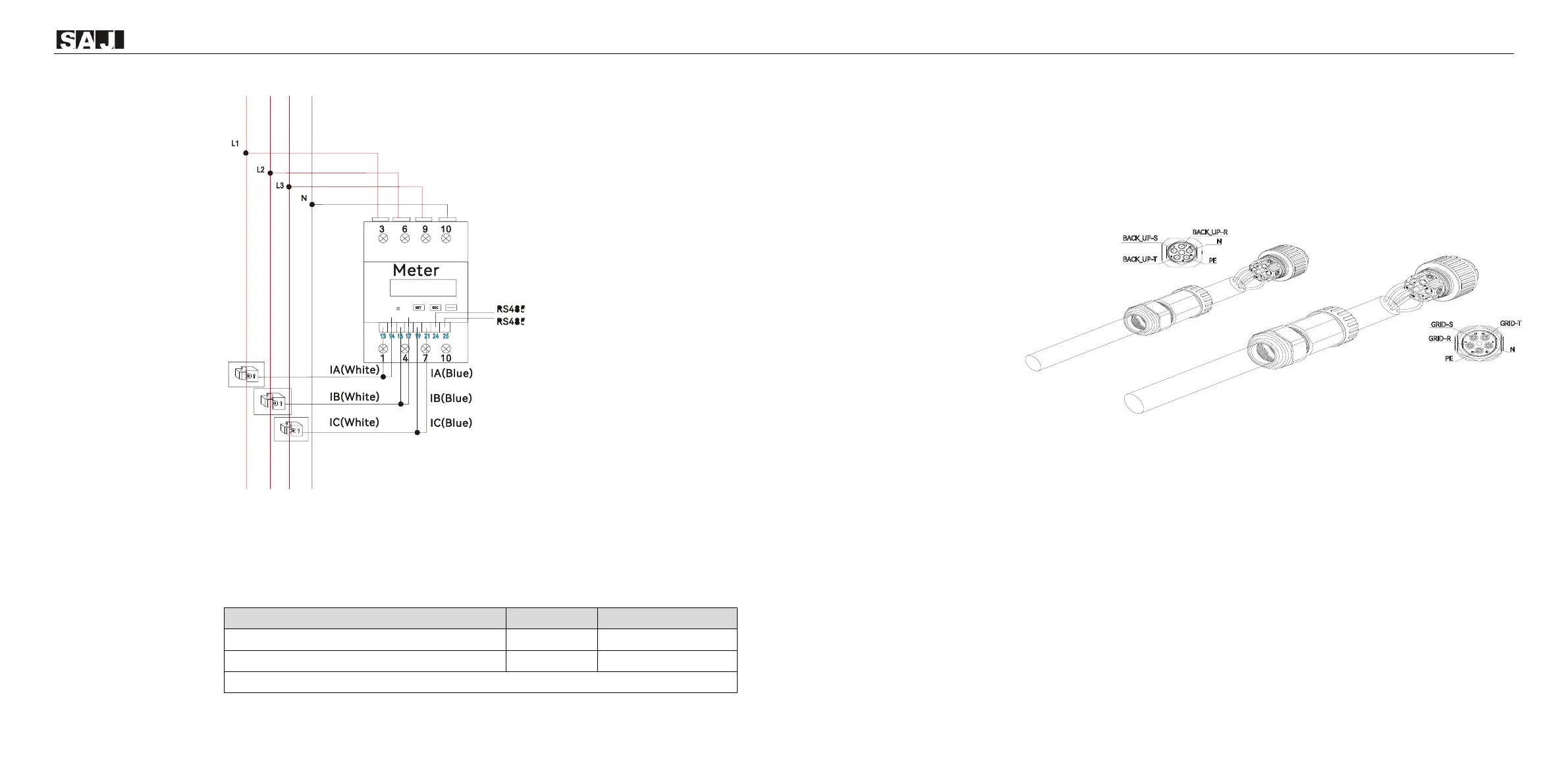
Procedure
1. Open the cable gland, insert cables through the hole, and connect the cables to the L1, L2, L3, PE, and
N terminals.
ATTENTION: (Australia only) Do NOT connect the PE terminal of the BACK-UP port.
ATTENTION: If the grid cables are not connected correctly, an error “Master Grid Phase Error” will occur.
For details, refer to Chapter 7 “Troubleshooting”. If this error occurs, switch the position of L2 and L3
cables.
2. Connect the cables to the BACK-UP and GRID ports on the inverter.
① Insert the cables and tighten the locknut in each cable.
② Install the protective covers to the cable connectors.
③ Tighten two screws to secure each connector tightly.
 Loading...