RS232 Communication (GPRS/ Wi-Fi /4G)
5.3 AC Connection
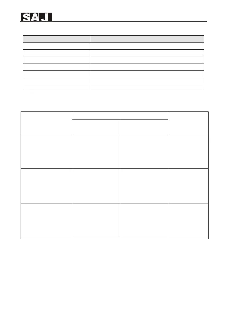
Table 5.3 Specifications for interface
Cross-sectional area of cables(mm²)
Recommender
additional grounding
cable size (mm²)
R6-
15K/17K/20K/22K/25K-T
2-32
R6-5K/6K/8K/10K/15K-T2-
32
-LV
10
R6-25K/30K/33K/36K-T3-32
R6-20K-T3-32-LV
16
R6-36K/40K/50K-T4-32
R6-25K/30K-T4-32-LV
16
Table 5.4 Recommended power grid connecting cable and additional grounding cable specification
Note: If the grid-connection distance is too far, please select AC cable with larger diameter
as per the actual condition.
5.3.1 AC side Electrical Connection
1. Ground of the inverter. After penetrating the external hex head screw through
OT terminal of the grounding line, screw in the grounding port of enclosure of the
inverter in clockwise direction and make sure it’s screwed up tightly.
 Loading...