5.4.1 Earth Fault Alarm
This inverter complies with IEC 62109-2 clause 13.9 for earth fault alarm monitoring. If an Earth Fault Alarm
occurs, the ring light will be lit up in red and error code <31> will be displayed on LED panel 1 until the error
being solved and inverter functioning properly.
Note:The inverter cannot be used with functionally earthed PV Arrays.
5.4.2 External AC Circuit Breaker and Residual Current Device
Please install a two pole circuit breaker to ensure the inverter is able to disconnect from grid safely. The
integrated leakage current detector of inverter is able to detect the real time external current leakage. When a
leakage current detected exceeds the limitation, the inverter will be disconnected from grid quickly.
The inverter does not require an external residual current device, as it has integrated with a RCMU. If local
regulations require the application of external residual current device, either type A or type B RCD is
compatible with the inverter. The action current of external residual current device should be 300mA.
Recommended breaker specification
R6-9-10K-S2-X,R6-9-10K-S3, R6-10K-S3-A
Notice: Do not connect multiple inverters to one AC circuit breaker.
Table 5.3
Recommended circuit breaker specification
5.4.3 Multiple Inverter
Combinations
5.5 DC Side Connection
· Make sure the PV array is well insulated to ground before connecting it to the inverter.
Conductor cross-sectional area of cables(mm²)
External cable
diameter(mm)
Outdoor multi-core copper wire
cable, complying with 600Vdc
Table5.4
Recommended specifications of DC cable
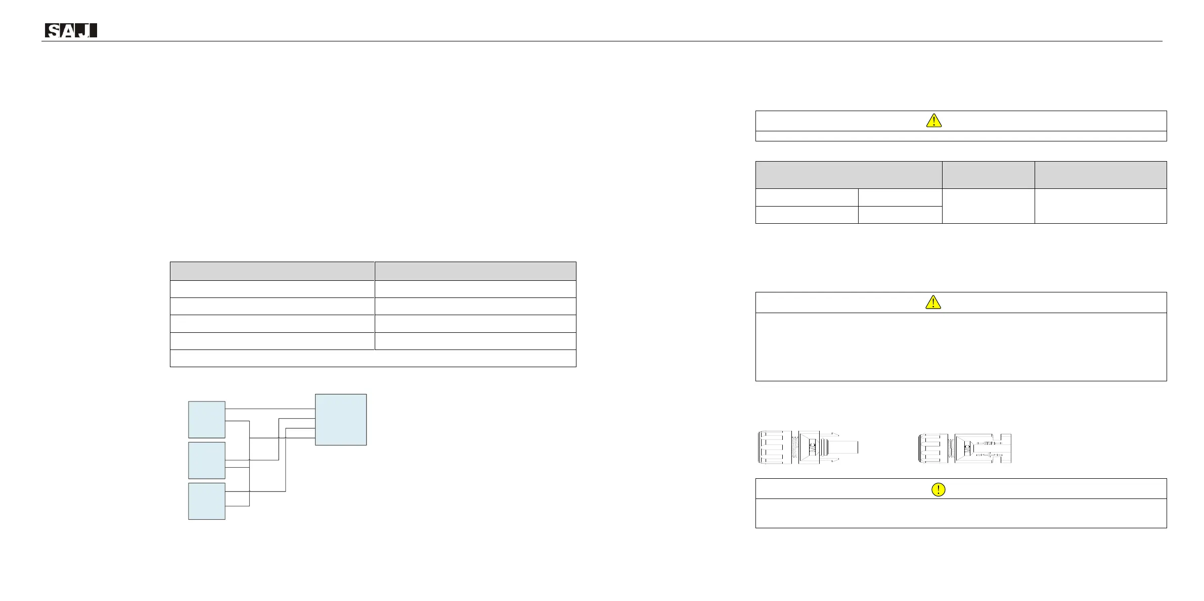
5.5.1 PV Connector Assembly
Dangerous to life due to electric shock when live components or DC cables are touched.
· The PV panel string will produce lethal high voltage when exposed to sunlight. Touching live DC cables results in death or
lethal injures.
· DO NOT touch non-insulated parts or cables
· Disconnect inverter from voltage sources.
· DO NOT disconnect DC connectors under load.
· Wear suitable personal protective equipment for all work.
DC connector is made up of positive connector and the negative connector
Figure 5.6
Positive connector
& Negative connector
· Please place the connector separately after unpacking in order to avoid confusion for connection of cables.
· Please connect the positive connector to the positive side of the solar panels, and connect the negative connector to the
negative side of the solar side. Be sure to connect them in right position.
Inverter
1 Phase
Inverter
1 Phase
Inverter
1 Phase
Test Circuit
Connection
3 Phase
A
B
C
N
The inverter should not be installed in multiple phase
combinations. If any such multiple inverter combination is
not tested,it should not be used or external devices
should be used in accordance with the requirements of
AS/NZS 4777.1
 Loading...