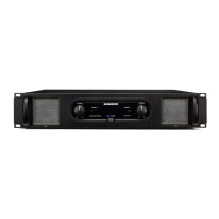
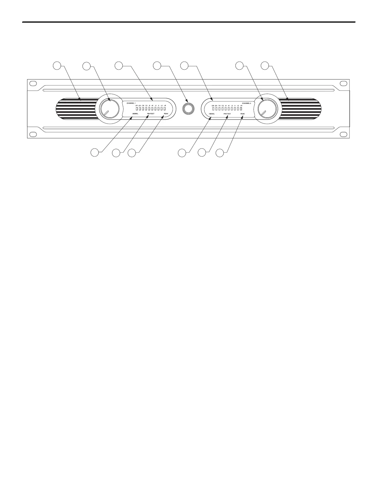
Guided Tour - Front Panel
- The Servo Series amplifiers stay cool thanks to their twin, forced-air cooling tunnels. Cool air is drawn through
the front panel fan vents, reducing the temperature of the internal components while forcing the heat out the rear vents.
The fans will actually sense the internal temperature and adjust their speed to maintain the optimum cooling conditions.
2: Channel input level controls
- These 42-position detented controls allow you to precisely adjust the input level of the
signal arriving at the rear-panel input jacks (see #1 and #5 on the following page). At their fully counterclockwise posi-
tion (labeled “MIN”), the signal is attenuated by 80 dB (essentially completely off). At their fully clockwise position (labeled
“MAX”), the signal is at unity gain (that is, no attenuation). When +4 dBu of signal arrives at the input jacks and the Channel
input level controls are set to their fully clockwise position, the Servo Series delivers full power output.
- These ten-segment LED meters continuously monitor the power output level for the corresponding chan-
nel. For convenience, the segments are labeled, from left to right, -24 dB, -20 dB, -16 dB, -12 dB, -8 dB, -4 dB, -2 dB. O, +2 dB
and +4 dB (PEAK). The right (PEAK) segment lights whenever the channel is outputting signal at full strength. For the best
signal-to-noise ratio, the right (PEAK) segment should light occasionally during peak levels; if it lights frequently, you may
be overloading the amplifier and a distorted (“clipped”) signal is probably being output. If this occurs and backing off the
Input Level control delivers too low an output level for your application, consider using Bridged mode (see the “Bridged
Mode” section on page 8 in this manual for more information).
- Use this to power the Servo Series on or off. The internal LED lights whenever the Servo Series is powered
- The front panel LED indicators continuously monitor the power output level for the corresponding channel.
The SIGNAL LED lights whenever output signal is present.
- This goes on for approximately five seconds whenever the Servo Series is powered on and then turns
off (you’ll hear a “click” when it does so). The Protection LED will also light when overheating or other severe problems occur
(see page 6 in this manual for more information). It is normal for the Protection LED to fade slowly when the amp is pow-
ered off. When lit, no signal is provided to any connected speakers, thus muting them and preventing any “thump” from
occurring. For a complete description of the conditions under which this light goes on, see the section entitled “The Servo
Series Protection Circuitry” on page 7 of this manual.
- The PEAK segment lights whenever the channel is outputting signal at full strength. For the best signal-
to-noise ratio, the right (PEAK) segment should light occasionally during peak levels; if it lights frequently, you may be
overloading the Servo Series and a distorted (“clipped”) signal is probably being output. If this occurs and backing off the
Input Level control delivers too low an output level for your application, consider using Bridged mode (see the “Bridged and
Parallel Modes” section on page 8 in this manual for more information).
 Loading...