NETWORK PTZ CAMERA User Guide
15
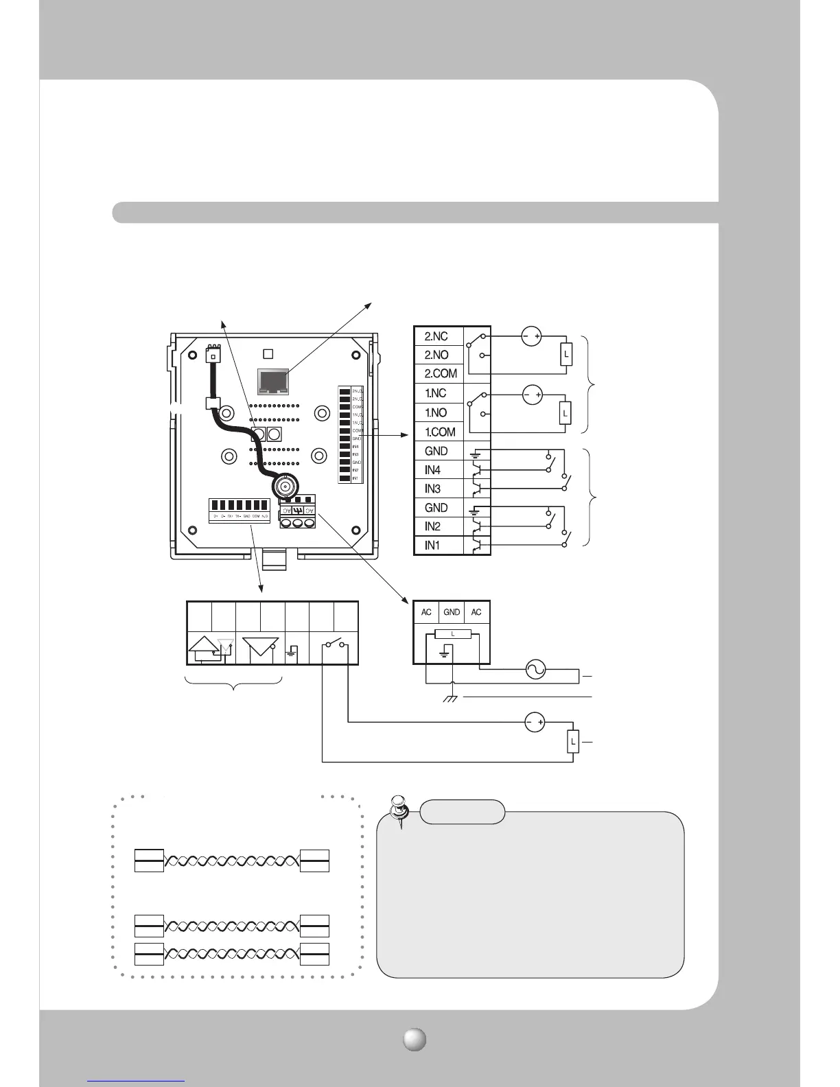
2.3. Camera Wiring Interface Board (Sold Separately)
· RS485 Communications
· RS422 Communications
Camera
Camera
D+
D-
D+
D-
59
59
59%
59%
59%
59%
39%
39%
Controller
Controller
Control Signal Connection
For the camera wiring, please refer to the picture below. The camera’s wiring interface board
is equipped in a housing and bracket that are sold separately.
t5IFNBYJNVNQPXFSDBQBDJUZPGUIFBMBSNBOE
"69PVUQVUTJT7%$"7"$"BOE
250VAC/0.25A.
t5PDPOOFDUQSPEVDUTPWFSUIFDBNFSBTDBQBDJUZ
please use an additional relay device.
t$POOFDUJOHUIFQPXFSDPOOFDUPSBOE(/%
incorrectly to the NC/NO and COM ports can
cause a short circuit which may lead to fire and
damage the camera.
Caution
Communications and AUX
D+ D- TX+ TX- GND
A_COM A_NO
Refer to Control Signal
Connection Diagram
(Below)
Power Supply
AC24V 2.5A
Alarm
ETHERNET
Audio IN/OUT
Alarm Output
Alarm Input
Power Input
AUX Output
Ground
Video OutputVideo Output
 Loading...