24 S&C Instruction Sheet 765-500
Installation
a. Open and close the switch and examine the
interrupter and blade alignment. The inter-
rupter must be parallel to the sweep of the
blade.
b. Partially open the switch. The following
conditions should be met:
• A ¹⁄c₂ minimum clearance between the
top of the opening cam and the bottom
of the closing lever, at their closest point.
• A ¹⁄c₂ minimum clearance between the
top of the opening lever and the bottom
of the closing cam.
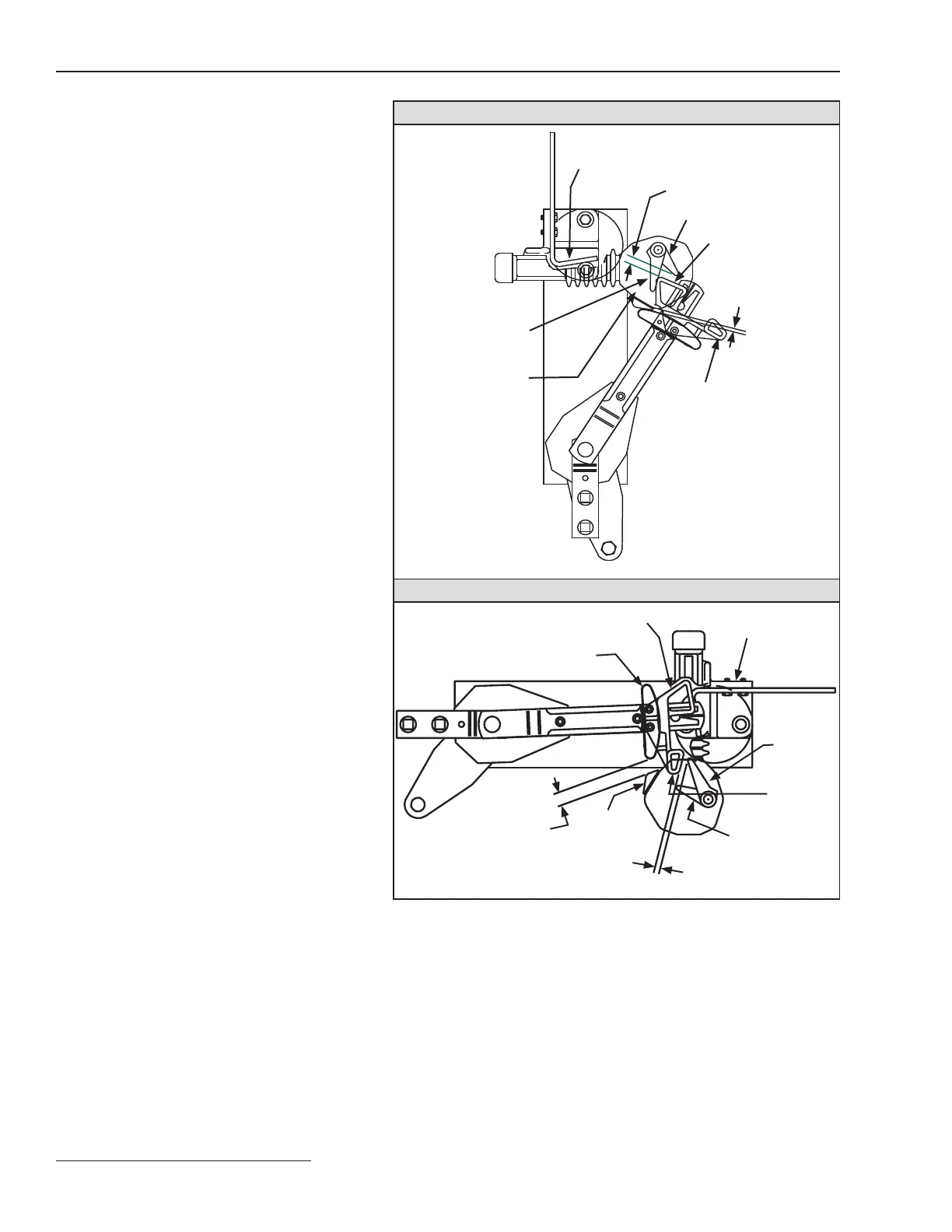
c. Open the switch and place the blade in the
position shown in Figure 25, View A. The
following conditions should be met:
• A ¹⁄₆₄ minimum clearance between the
opening cam and the opening lever.
• A clearance between ³⁄c₂ and ⁷⁄c₂ between
the shunt contact and the interrupter
housing at the beginning of the closing
sweep.
d. Place the switch in the fully-closed position.
The following conditions should be met:
• A clearance of ¹⁄₁₆– >⁄c₂ between the clos-
ing cam and the closing lever.
• A ¹⁄₂ minimum clearance between the
blade shunt contact and the interrupter
housing contact.
View A, During Closing
Opening lever
Opening cam
Closing cam
Main contact
¹⁄₆₄ min.
³⁄₃₂ to ⁷⁄₃₂
Closing
lever
Interrupter
housing
View B: Closed Position
Interrupter
housing
contact
Blade shunt contact
Opening cam
Jaw contact
casting
Closing
lever
Opening lever
¹⁄₁₆ to ⁹⁄₃₂
¹⁄₂ min.
Closing
cam
Figure 25. Operating checkpoints for switches rated 14.4 kV.
 Loading...


