S&C Instruction Sheet 765-500 19
Installation
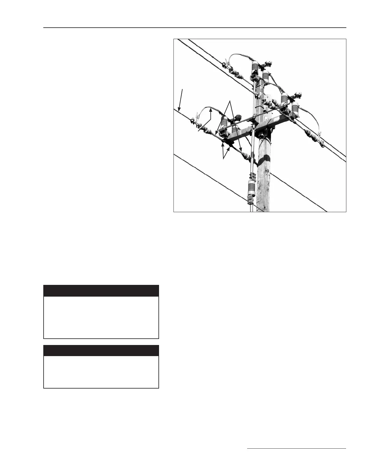
Figure 18. Dead-ending bracket (triangular mounting configuration
shown).
Extension link assemblies
Dead-end brackets
Jumper
Line conductor
Dead-Ending Conductors
Dead-ending provisions are standard on
Omni-Rupter switches that have upright, upright
(extra mounting pole clearance), or triangular,
mounting configurations. When dead-ending to
these brackets, a pole band and extension-link
assemblies
are required. See Figure 18.
Maximum dead-end loading for S&C dead-
ending brackets on switches with steel bases:
a. 2000 pounds per conductor where pull-off
forces are applied to only one side of the
switch.
b. 8000 pounds per conductor where equal
pull-of forces are applied to both sides of
the switch.
c. 1500 pounds per conductor for upright
switches with extra mounting pole clear-
ance where pull-off forces are applied to only
one side of the switch.
Maximum dead-end loading for S&C dead-
ending brackets on switches with insulated
bases:
a. 750 pounds or 500 pounds per conductor,
14.4-kV and 25-kV respectively, where pull-
off forces are applied to only one side of the
switch, including upright switches with extra
mounting pole clearance.
b. 8000 pounds per conductor for 14.4-kV and
25-kV switches, where equal pull-off forces
are applied to both sides of the switch.
Connecting High-Voltage
Conductors
Ç DANGER
Conductors must be de-energized and
grounded in accordance with standard
system operating practice.
Failure to do so can result in serious
injury or death.
NOTICE
To avoid overloading the terminal pads, S&C
recommends making the jumper connection
to the line conductor before securing jumper
fasteners to the terminal pad.
A pole band can be specified by adding suffix “-P1”
to the catalog number. Extension-link assemblies can be
provided by adding suffix “-D” to the catalog number of the
switch, or equivalent user-furnished extension means may
be used.
 Loading...


