— 12 —
MECHANICAL DISASSEMBLIES
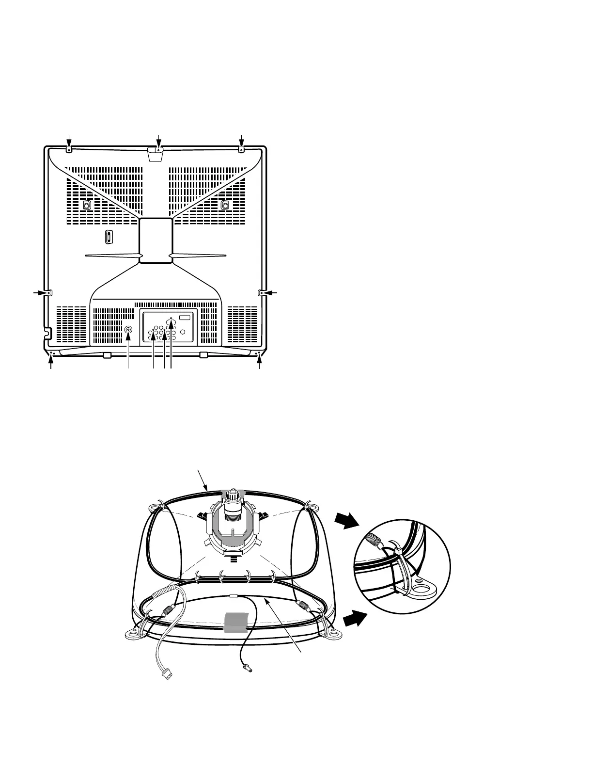
CABINET BACK REMOVAL
1. Refer to Figure 1, remove 11 screws.
2. Pull off cabinet back and remove.
CHASSIS REMOVAL
1. Remove cabinet back.
2. Discharge the picture tube anode (2nd anode lead) to the
dag coating (picture tube grounding lead).
3. Disconnect degaussing coil socket (KD), picture tube
socket, deflection yoke connector (KX), speakers
connector (KSP), picture tube ground lead, and 2nd
anode lead.
4. Remove chassis completely by sliding it straight back.
PICTURE TUBE REMOVAL
CAUTION: Do not disturb the deflection yoke or magnet
assembly on the picture tube neck. Care must be taken to
keep these assemblies intact, unless picture tube is being
replaced. Discharge the picture tube to the coating before
handling the tube.
1. Remove chassis, referring to Chassis Removal instructions.
2. Place cabinet’s front face down on a soft surface.
3. Remove the screw on each corner of the picture tube and
GENTLY lift the picture tube out of the cabinet.
4. Install a replacement picture tube in reverse order.
Properly install the degaussing coil and picture tube
grounding lead on the picture tube. See Figure 2.
Note: If Picture Tube is being replaced, mount the Degaussing
Coil properly on the tube. See Figure 2.
Figure 2. Picture Tube Removal
Figure 1. Cabinet Back Removal
 Loading...