
Do you have a question about the Saswell T21HTW-0 and is the answer not in the manual?
| Power Supply | 230V AC |
|---|---|
| Temperature Range | 5°C to 35°C |
| Accuracy | ±0.5°C |
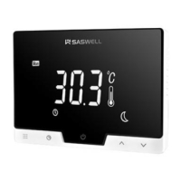
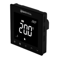
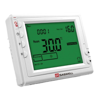
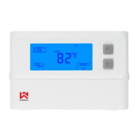
| Display | LCD |
| Backlight | Yes |
| Child Lock | Yes |
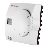
| Installation | Wall-mounted |
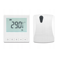
| Power Source | Wired |
| Programmable | Yes |
Details power supply, terminal load, temperature range, accuracy, dimensions, and color.
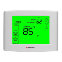
Highlights LCD display, simultaneous storage, fan control, battery operation, and air filter indicator.
Covers turning off power, reading manual, professional installation, voltage limits, and wiring codes.
Includes turning off power, labeling wires, and removing the existing thermostat unit.
Instructions for opening the cover, installing the base, and finishing wiring.
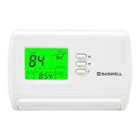
Explains how batteries maintain time and display during AC power loss.
Illustrates terminal connections for power supply, relays, and system components.
Steps to test fan operation and system response in HEAT mode.
Details the function of each button and system control switch on the thermostat.
Guides on setting the clock, reviewing filter days, and cleaning filter warnings.
Addresses issues like blank display or erratic operation, suggesting resets.
Covers selecting cooling/heating cycle rates and display backlight options.
Settings for filter replacement reminders and temperature calibration adjustments.
Options for °F/°C display, temperature recalibration, and compressor lockout delay.
Allows user selection for auxiliary heating turn-on temperature relative to set-point.
Details on selecting fast (FA) or slow (SL) cooling and heating cycles.
Configuration for display backlight, filter time, and temperature units (°F or °C).