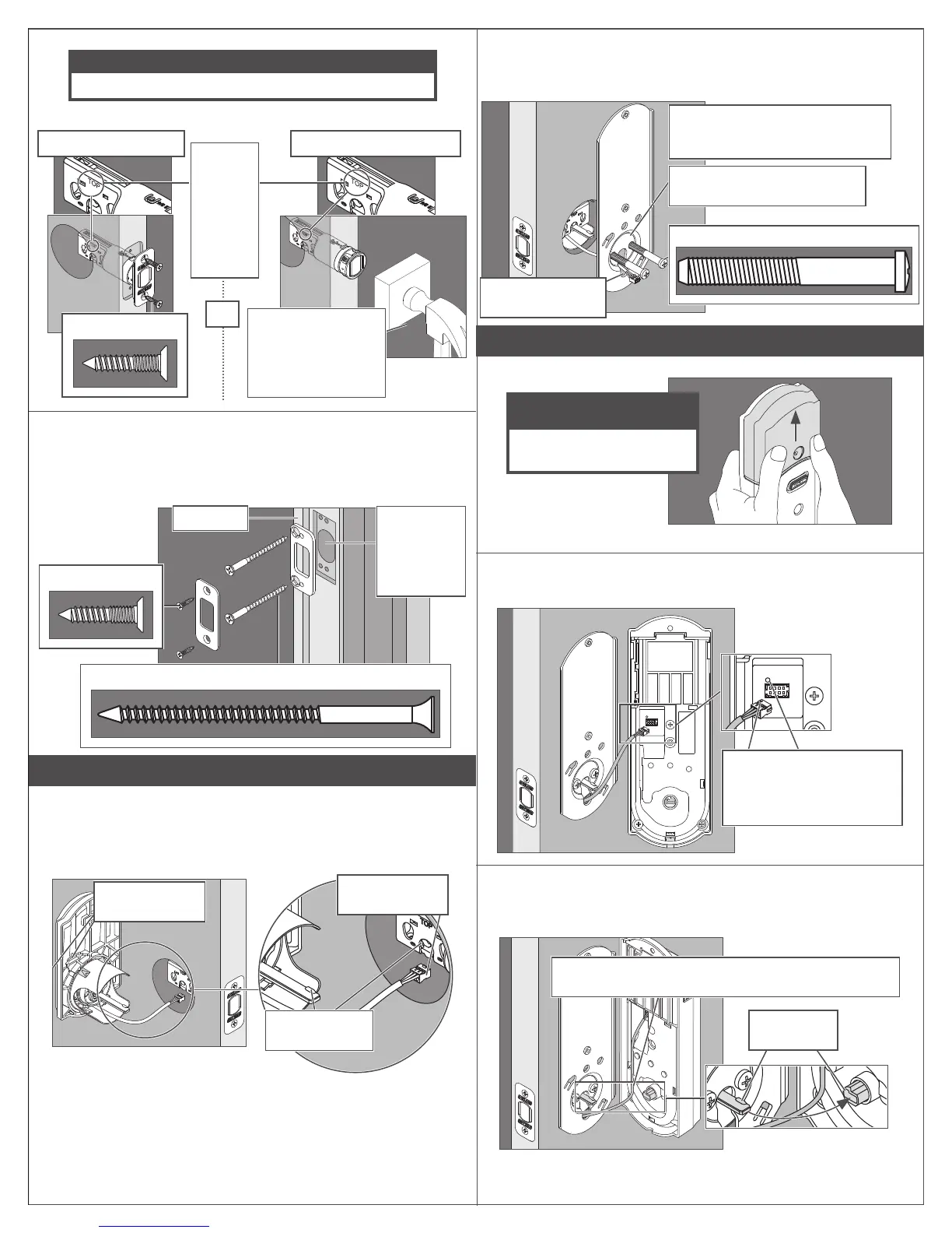
3c Install the bolt into the door.
IMPORTANT!
Retract the bolt before continuing to step 3c!
Choose the picture below that matches your door.
FIgure A: Mortise Figure B: No Mortise
Use a block of wood
and a hammer (not
included) to tap the
bolt into place. You
don’t need to use the
screws.
Actual Size (2)
OR
Make
sure the
word
TOP
faces up
when
installing
the bolt.
3d Install the strike into the frame.
Install all the parts shown for maximum security.
L In order to maintain BHMA Grade 2, you must install the included
reinforcement plate and strike.
L The reinforcement screws may not fit on doors with sidelights.
Actual Size (2)
Reinforcement Screws: Actual Size (2)
Door Stop
Make sure
this hole is at
least 1” (25
mm) deep.
4 Install the Touchscreen Assembly
4a Install the Touchscreen on the outside of the door.
L The clips snap into the crossbore (see step 2) to assist in holding
the keypad on the door.
L The Touchscreen Assembly should install smoothly. If it does not,
check that the bolt is set to the correct backset (see step 2).
Clips snap into
the crossbore.
Align the tab
with the notch.
Route the cable
under the bolt.
L NOTE: If you have a crossbore (see step 2) that is slightly less
than 2Z\,” (54 mm), the lock may not install smoothly. You can
remove the spacer. Always remove the spacer for a 1Z\x” (38 mm)
crossbore.
4b Install the Support Plate on the inside of the door.
L Make sure the Touchscreen and Support Plate are straight on the
door before tightening the screws. Tighten screws fully to prevent
the lock from moving over time.
TOP
Make sure the indented circle is
facing the door.
Have someone hold the Touchscreen
on the outside of the door while you
tighten the screws.
Actual Size (2)
Route the cable
through the slot.
5 Install the Inside Assembly
5a Remove the battery cover from the Inside Assembly.
ELECTROSTATIC
DISCHARGE WARNING!
Avoid contact with the
circuit board!
L Do not remove the battery tray (not shown).
5b Connect the cable to the Inside Assembly.
L Locate the screws in step 5d before beginning this step so they will
be handy when you need them.
The connector fits only one
way. Match the dot on the
connector with the dot on the
circuit board.
5c Install the Inside Assembly.
1. Align the tab with the notch as shown.
2. Route the cable into the channel.
3. Then slide the Inside Assembly towards the door.
Align tab
with notch.
Route the cable into the channel to avoid crimping the cable.

 Loading...